Progressive brake light system

a technology of brake light and progressive brake, which is applied in the direction of vehicle components, signalling/lighting devices, optical signalling, etc., can solve problems such as not alleviating

Inactive Publication Date: 2003-06-03
VARIABLE STATUS BRAKE LIGHT LLC DUNCAN REZNIK LARI
View PDF18 Cites 41 Cited by
  • Summary
  • Abstract
  • Description
  • Claims
  • Application Information

AI Technical Summary

Benefits of technology

It is believed that the progressive brake light system of the invention provides a number of advantages over existing brake light systems. The brake light indicator not only acts a third brake light, it also provides an indication of the degree of application of the brakes of a vehicle. Accordingly, the driver of a following vehicle is in a better position to determine how hard the brakes of his or her vehicle are to be applied. Further, the brake light system of the invention can be tailored to a particular vehicle and to any changes to its braking profile during the life of the vehicle.

Problems solved by technology

However, the use of this third brake light does not alleviate a problem associated with braking in general and that is the problem of a following driver not being able to determine whether the vehicle in front is being braked lightly or being braked under emergency conditions.

Method used


Image

  • Progressive brake light system
  • Progressive brake light system
  • Progressive brake light system

Examples


Embodiment Construction

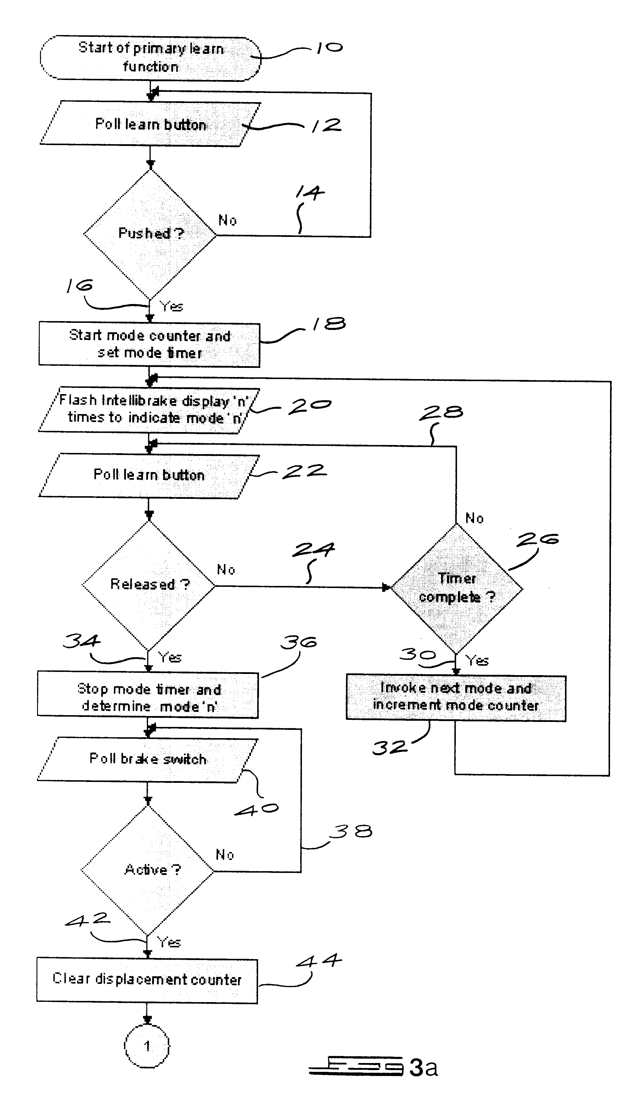
The crux of the invention lies in providing a light arrangement which is arranged to illuminate or extinguish in a pre-determined sequence in response to the degree of application of the brakes of a vehicle, and in particular to a control module that is able to "learn" the individual characteristics of the brake pedal for a particular vehicle so as to control the illumination and extinguishing of the light arrangement.

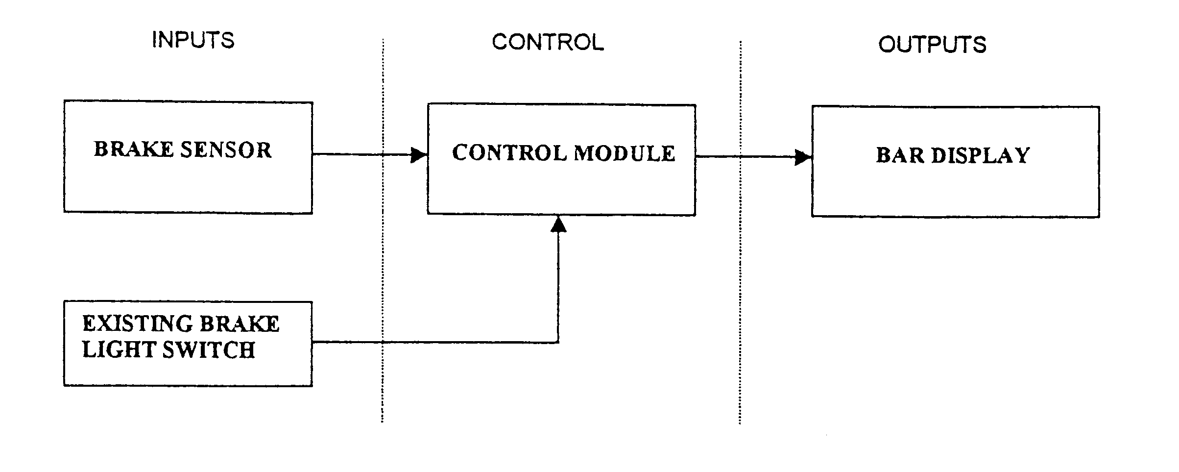
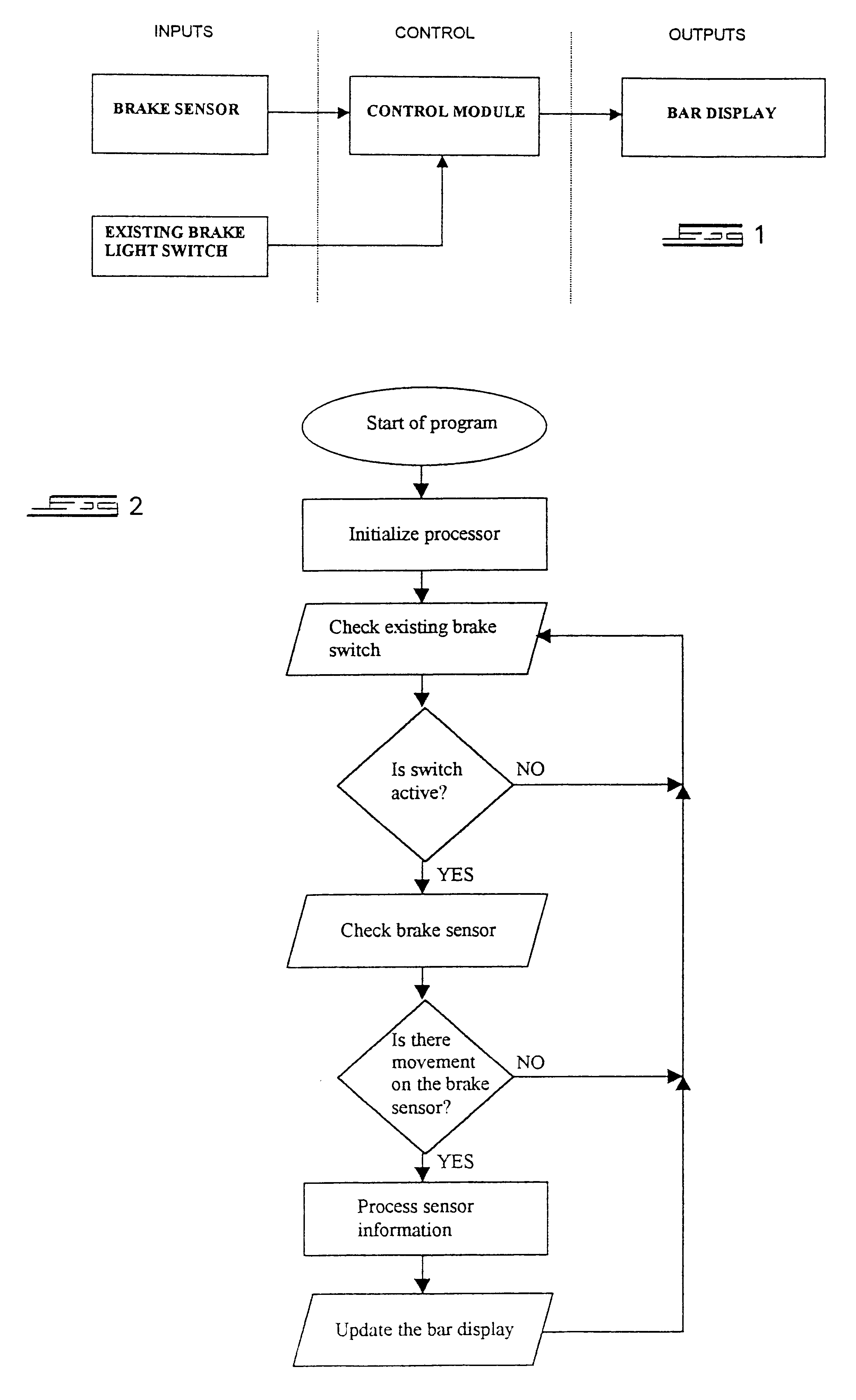
Referring to FIG. 1, the essential components of the progressive brake light system of the invention consist of a brake sensor, control module and bar display or brake light display which is arranged to work in conjunction with an existing brake light switch of the vehicle.

Various sensor options such as optical sensors, potentiometer or resistance sensors, speed transducers and accelerometers, strain gauges and linear displacement sensors, for example, can be used. The preferred sensor, however, is an optical sensor of the type commonly used in a PC mouse to control th...


PUM


Abstract

The progressive vehicle brake light system of the invention consists of a brake sensor arranged to sense the travel of a brake pedal and a brake light display arranged to illuminate or extinguish in sequence or progressively in response to the travel of the brake pedal. A microcontroller is provided for receiving a signal from the brake sensor and controlling the brake light display accordingly. The brake sensor is typically an optical sensor utilizing infrared transmitters and receivers arranged to sense the distance and direction of travel of the brake pedal. The brake light display consists of a row of light emitting diodes (LEDs) which are arranged to illuminate from the opposite ends towards the middle as the brake pedal is depressed and to extinguish in reverse sequence when the brake pedal is released.

Description

BACKGROUND TO THE INVENTIONThis invention relates to a progressive brake light system.The use of a so-called third brake light in motor vehicles has become popular in recent times. The third brake light is typically positioned so as to be more visible to a driver of a following vehicle. However, the use of this third brake light does not alleviate a problem associated with braking in general and that is the problem of a following driver not being able to determine whether the vehicle in front is being braked lightly or being braked under emergency conditions.According to the invention a progressive brake light system for a vehicle comprises:sensor means arranged to sense the degree of application or release of the brakes of the vehicle.a brake light display arrangement comprising a plurality of individual lights or light units arranged to be illuminated or extinguished in sequence or progressively, in response to the degree of application or release of the brakes, respectively; anda...

Claims


Application Information

Patent Timeline
Patent Type & Authority Patents(United States)
IPC IPC(8): B60Q1/44
CPCB60Q1/444B60Q1/44
Inventor COHEN, SAUL LAWRENCEKESSEL, GARY NATHANGORDON, LARRY RUBIN
Owner VARIABLE STATUS BRAKE LIGHT LLC DUNCAN REZNIK LARI
Why Eureka
Try Eureka