Sealable fastener with sealant delivery passageway to circumferential sealant channel

a sealant delivery and sealing technology, applied in the field of sealable fasteners, can solve the problem that no truly effective means have been provided for creating a seal

Inactive Publication Date: 2003-07-08
KUBLER FR L +1
View PDF6 Cites 35 Cited by
  • Summary
  • Abstract
  • Description
  • Claims
  • Application Information

AI Technical Summary

Benefits of technology

It is still another object of the present invention to provide such a fastener which is inserted into a receiving structure in the same way and with the same tool or tools used to insert an otherwise similar fastener, and through which a flowable sealant can be rapidly, easily and reliably delivered.
It is finally an object of the present invention to provide such a fastener which is relatively inexpensive to manufacture and to install in a receiving structure.
The circumferential channel optionally is located substantially midway between the shank first end wall and the shank second end wall. Where the shank side wall includes fastener threads, the circumferential channel preferably is deeper than the fastener threads. The sealable fastener preferably includes several exit ports opening into the circumferential channel, the exit ports being circumferentially spaced apart along the circumferential channel for enhancing the speed and evenness of distribution of sealant into the circumferential channel.

Problems solved by technology

A problem with these prior fasteners has been that no truly effective means has been provided for creating a seal between the shank of the fastener and the surrounding receiving structure to reliably prevent liquid from flowing along the shank from one side of the receiving structure to the other.

Method used


Image

  • Sealable fastener with sealant delivery passageway to circumferential sealant channel
  • Sealable fastener with sealant delivery passageway to circumferential sealant channel
  • Sealable fastener with sealant delivery passageway to circumferential sealant channel

Examples


Embodiment Construction

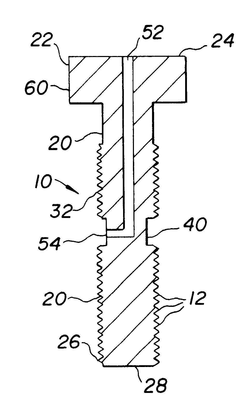
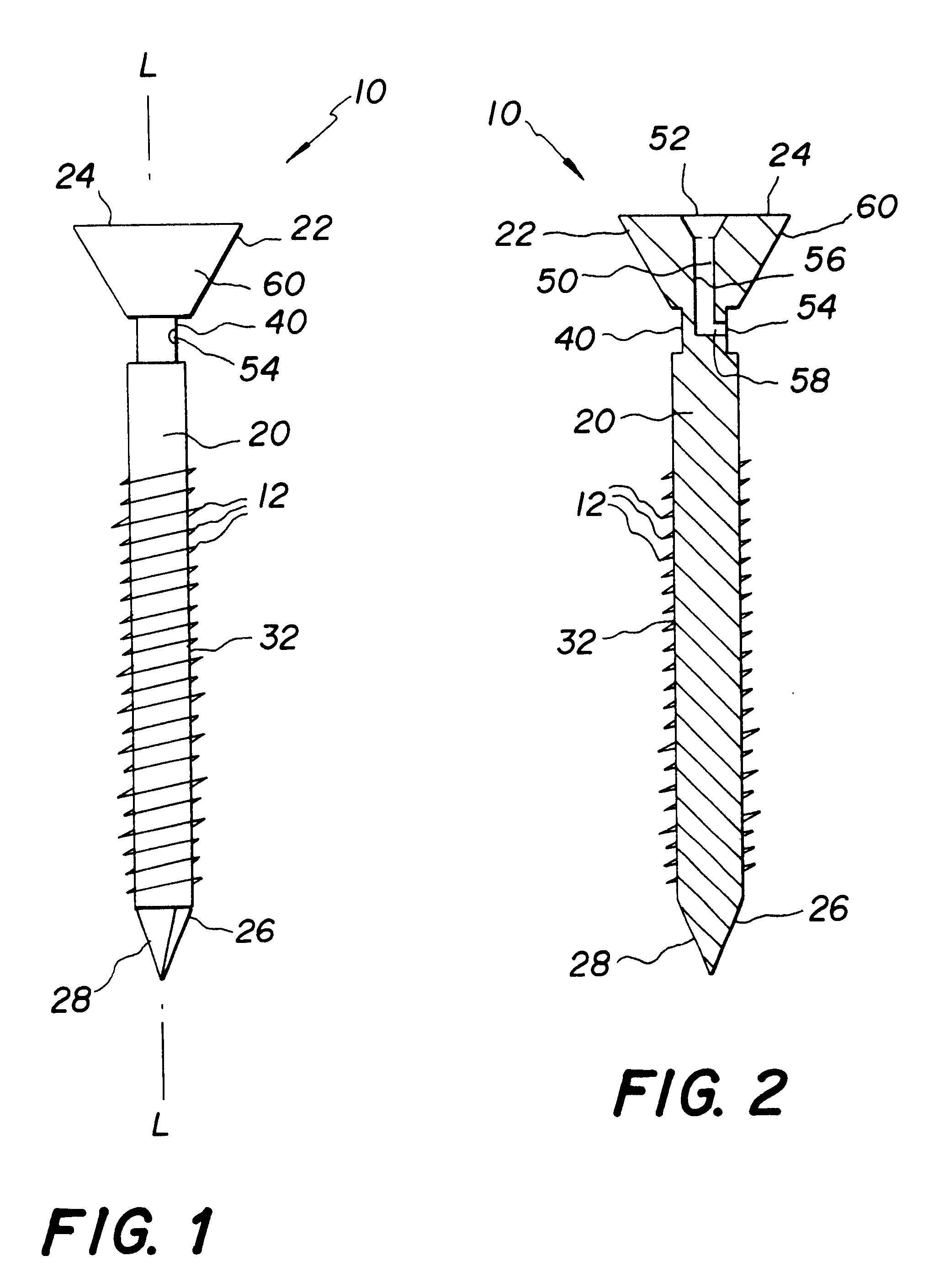
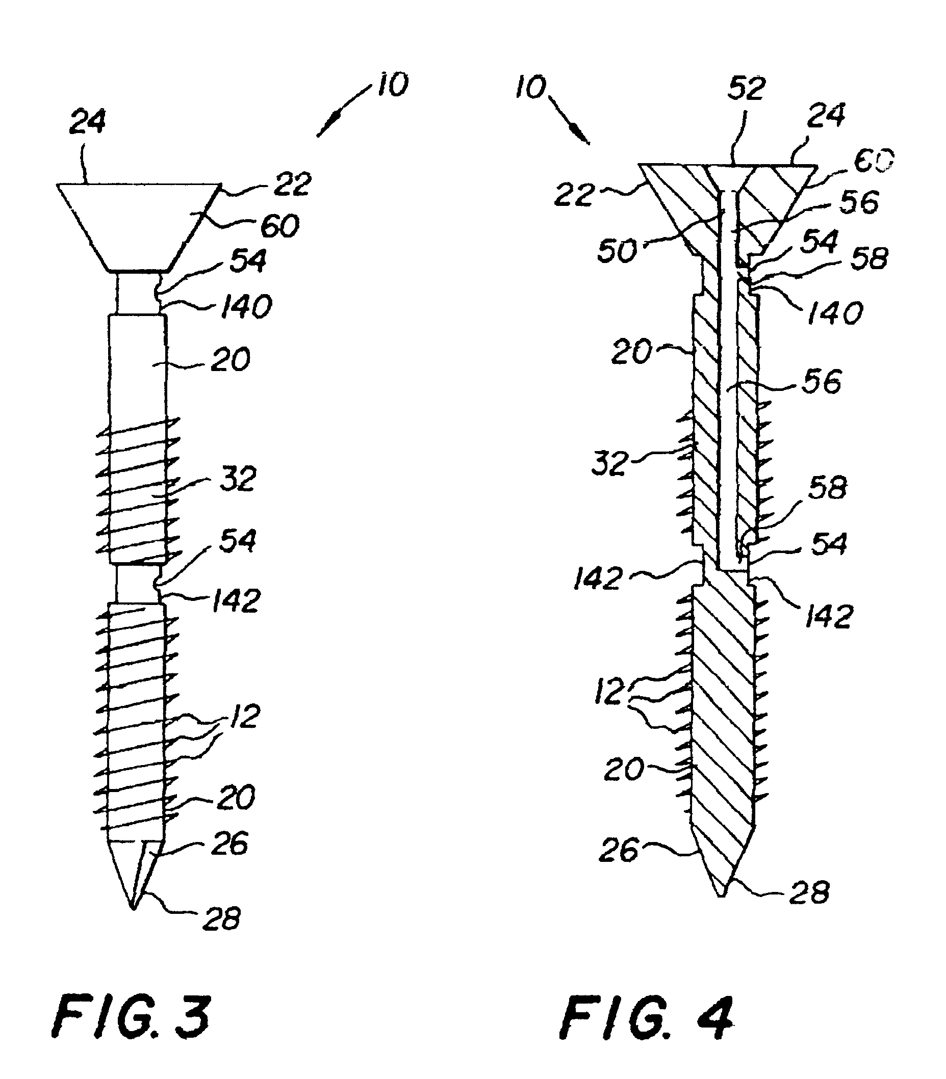
Referring to FIGS. 1-23, a sealable fastener 10 is disclosed including a fastener shank 20 having a shank first end 22 with a shank first end wall 24 and a shank second end 26 with a shank second end wall 28, a shank side wall 32 extending between shank first end 22 and shank second end 26, a continuous, fully circumferential channel 40 recessed into shank side wall 32, and including a sealant delivery passageway 50 having a passageway entry port 52 in the shank first end 22 and extending both longitudinally and laterally to a passageway exit port 54 opening into circumferential channel 40.

The sealant delivery passageway 50 may be a bore in fastener shank 20 extending from entry port 52 substantially coaxially with or substantially parallel to the shank longitudinal axis L opening through exit port 54 into circumferential channel 40 or optionally opening through two separate exit ports 54 into first and second circumferential channels 140 and 142, respectively. In the latter instanc...


PUM


Abstract

A sealable fastener for insertion into a fastener opening bore in a receiving structure includes a fastener shank including a shank first end having a shank first end wall and a shank second end having a shank second end wall, a shank side wall extend between the shank first end wall and the shank second end wall and a circumferential channel recessed into the shank side wall; and a sealant delivery passageway having a passageway entry port in the shank first end and extending to a passageway exit port opening into the circumferential channel; so that a flowable sealant injected into the passageway entry port flows through the sealant delivery passageway and exits through the passageway exit port and flows into and around the circumferential channel, creating a circumferential seal between the fastener shank and the fastener opening in the receiving structure.

Description

1. Field of the InventionThe present invention relates generally to the field of fasteners, particularly in the marine and construction industries, including screws, such as those used to construct boat hulls, bolts, such as concrete anchor bolts, and including rivets, nails and pins. More specifically the present invention relates to a sealable fastener including a fastener shank having shank first and second ends with shank first and second end walls, a longitudinal shank side wall and a continuous, fully circumferential channel recessed into the shank side wall, and including a sealant delivery passageway having a passageway entry port in the shank first end and extending both longitudinally and laterally to a passageway exit port opening into the circumferential channel. The sealant delivery passageway may be a bore in the shank extending substantially coaxially with or substantially parallel to the shank longitudinal axis, or may be a combination of fastener head bore through t...

Claims


Application Information

Patent Timeline
Patent Type & Authority Patents(United States)
IPC IPC(8): F16B33/00F16B35/06F16B35/04
CPCF16B33/004F16B35/041F16B35/06
Inventor KUBLER, FRANK L.DUCKER, III, ANDREW L.
Owner KUBLER FR L
Why Eureka
Try Eureka