
Mini-optics solar energy concentrator

a solar energy concentrator and solar energy technology, applied in the field of mini-optics solar energy concentrators, can solve the problems that the prior art neither teaches nor anticipates our application of solar energy conversion to electricity or any other form of energy, and neither teaches or anticipates our invention

Inactive Publication Date: 2003-08-21
DAVIDSON MARK +1
View PDF0 Cites 33 Cited by
  • Summary
  • Abstract
  • Description
  • Claims
  • Application Information

AI Technical Summary

Benefits of technology

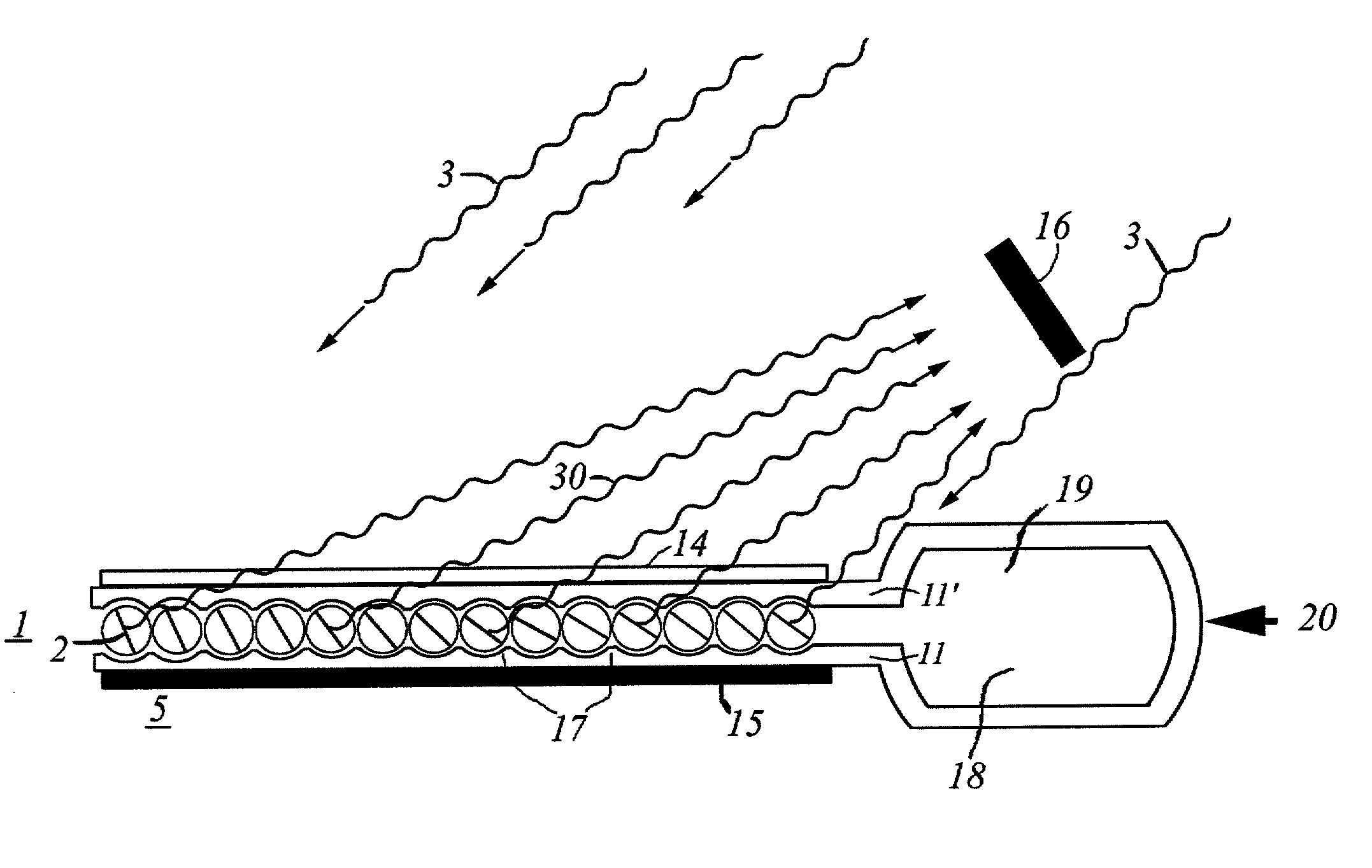
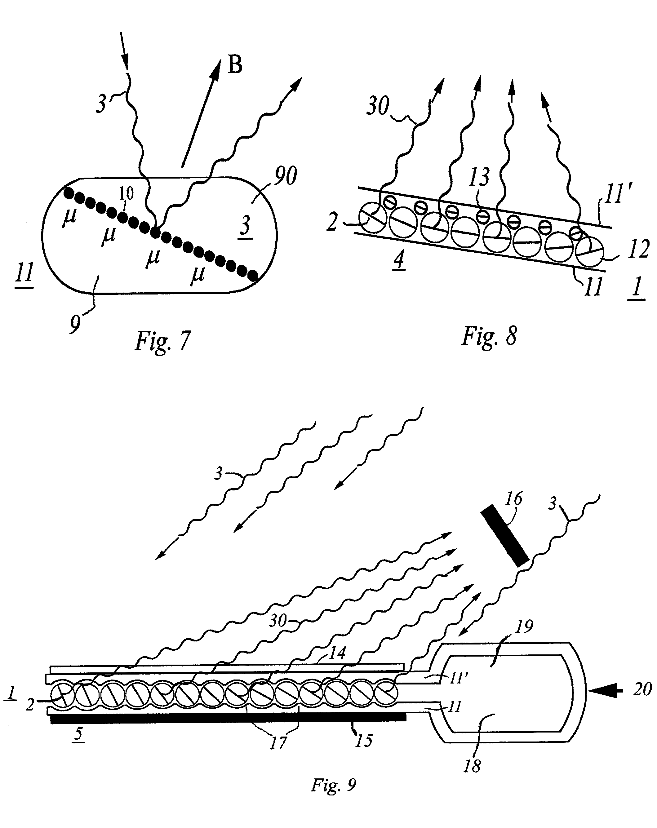
[0036] One object is to provide an inexpensive, light-weight, and flexible mini-optical light concentrator that can easily be attached to existing structures, and thus does not require the construction of a superstructure of its own.
[0037] Another objective is to provide a solar energy conversion system that is not only low capital cost, but that is also inexpensive to install.
[0040] Another object is to provide a means for unlocking the mini-mirror elements so that they may rotate freely when being guided into the proper orientation.
[0041] Another object is to provide an inexpensive system for photovoltaic conversion.
[0048] Another object is to provide a low-cost, tough, light-weight, concentrated efficient solare energy converter that is highly portable.
[0050] Another object is to provide a portable system that can easily go anywhere man can go, to track and concentrate the sun's energy.

Problems solved by technology

Furthermore the prior art neither teaches nor anticipates our application of the conversion of solar energy to electricity or any other form of energy.
In fact, the gyricon and separable ball prior art do not teach the focussing of light in any capacity.
While there are other such prior art teachings, none of them teaches or anticipates our invention.

Method used


Image

  • Mini-optics solar energy concentrator
  • Mini-optics solar energy concentrator
  • Mini-optics solar energy concentrator

Examples


Embodiment Construction

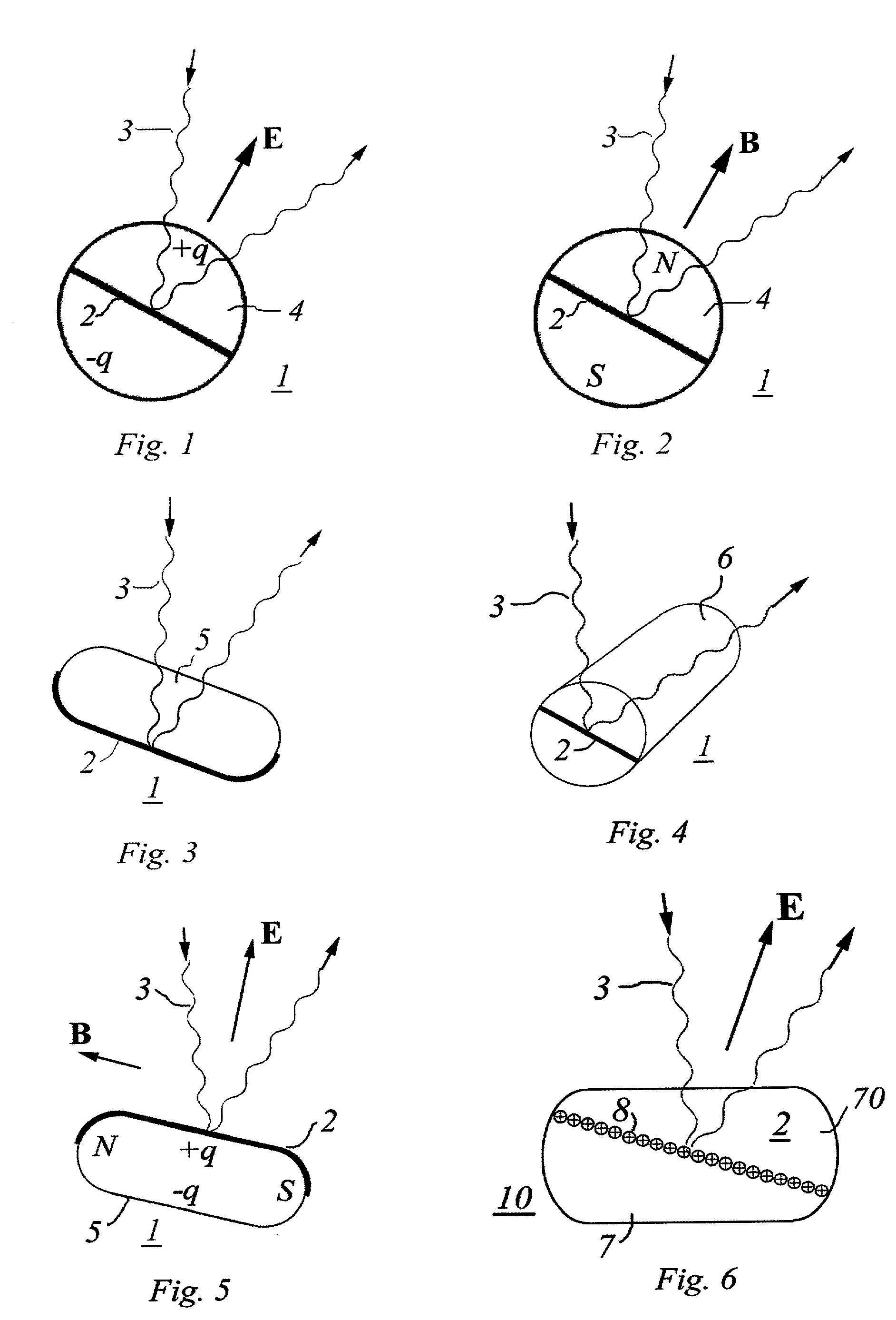
[0065] FIG. 1 shows a rotatable element 1 of a focussing planar mini-mirror with an equatorial flat reflecting surface 2 which reflects a wave beam of sunlight 3. The element 1 shown is a cross-sectional view of an electrically charged bipolar sphere 4 with charge +q in one hemisphere and charge -q in the opposite hemisphere, that is operated in the well-known electrical gyricon mode. This sphere 4 is one of a multitude of rotatable optical elements 1 which track the sun and focus the sun's light wave beam onto a collector by means of an electric field E.

[0066] FIG. 2 shows a rotatable element 1 of a focussing planar mini-mirror with a flat equatorial reflecting surface 2 which reflects a wave beam of sunlight 3. The element 1 shown is a cross-sectional view of a magnetically charged bipolar sphere 4 with north magnetic field N in one hemisphere and south magnetic field S in the other hemisphere, that is operated in the well-known magnetic gyricon mode. This sphere 4 is one of a mul...


PUM


Abstract

This invention deals with the broad general concept for focussing light. A mini-optics tracking and focussing system is presented for solar power conversion that ranges from an individual's portable system to solar conversion of electrical power that can be used in large scale power plants for environmentally clean energy. It can be rolled up, transported, and attached to existing man-made, or natural structures. It allows the solar energy conversion system to be low in capital cost and inexpensive to install as it can be attached to existing structures since it does not require the construction of a superstructure of its own. This novel system is uniquely distinct and different from other solar tracking and focussing processes allowing it to be more economical and practical. Furthermore, in its capacity as a power producer, it can be utilized with far greater safety, simplicity, economy, and efficiency in the conversion of solar energy.

Description

[0001] 1. Field of the Invention[0002] Due to an ever growing shortage of conventional energy sources, there is an increasingly intense interest in harnessing solar energy. A limiting factor in the utilization of solar energy is the high cost of energy converters such as photovoltaic cells. Our invention provides a low cost means for achieving affordable solar energy by greatly reducing the cost of solar concentrators which increase (concentrate) the density of solar energy incident on the solar energy converter. For example, for the purpose of generating electricity, a large area of expensive solar cells may be replaced by a small area of high-grade photovoltaic solar cells operating in conjunction with the inexpensive intelligent mini-optics of our invention. Thus our invention can contribute to the goal of achieving environmentally clean energy on a large enough scale to be competitive with conventional energy sources.[0003] Our invention is less expensive than conventional solar...

Claims


Application Information

Patent Timeline
IPC IPC(8): F24S23/70G02B26/02
CPCF24J2/1047F24J2/1052F24J2/1057F24J2/16F24J2/18F24J2002/1066Y02E10/47F24J2002/5437G02B26/026G02F1/19G02F1/29F24J2/541F24J2002/108F24S23/80F24S23/79F24S30/425F24S2023/872F24S23/82F24S2023/85F24S23/81F24S2030/11F24S23/77G02B26/0816
Inventor DAVIDSON, MARKRABINOWITZ, MARIO
Owner DAVIDSON MARK
Learn More