
Bicycle fork cartridge assembly

a technology for forks and mountain bikes, applied in the direction of shock absorbers, steering devices, cycle equipments, etc., can solve the problems of inability to provide both a compression lock-out feature and an easily accessible external damping adjustment control, existing mechanisms for providing external damping adjustment and compression lock-out require undue complexity

Inactive Publication Date: 2003-07-15
FOX FACTORY
View PDF38 Cites 295 Cited by
  • Summary
  • Abstract
  • Description
  • Claims
  • Application Information

AI Technical Summary

Problems solved by technology

However, prior art mountain bike suspension forks have failed to provide both a compression lock-out feature and external damping adjustment controls that are easily accessible while riding.
Further, existing mechanisms for providing external damping adjustment and compression lock-out require undue complexity.

Method used


Image

  • Bicycle fork cartridge assembly
  • Bicycle fork cartridge assembly
  • Bicycle fork cartridge assembly

Examples


second embodiment

FIG. 8 is an enlarged cross-section of a rebound adjustment and lock-out cap assembly of a suspension fork;

FIG. 9 is a cross-section of the cap assembly of FIG. 8, taken along the line 9--9 in FIG. 8;

FIG. 10 is a cross-section of a base valve assembly of the second embodiment;

third embodiment

FIG. 11 is a cross-section of a rebound adjustment, low speed compression adjustment and lock-out cap assembly of a suspension fork;

FIG. 12 is a top view of a low-speed compression adjustment knob of the cap assembly of FIG. 11;

FIG. 13 is a cross-section of the low-speed compression adjustment knob of FIG. 12, taken along the line 13--13 of FIG. 12;

FIG. 14 is a cross-section of a blow-off adjustment base valve assembly of the third embodiment;

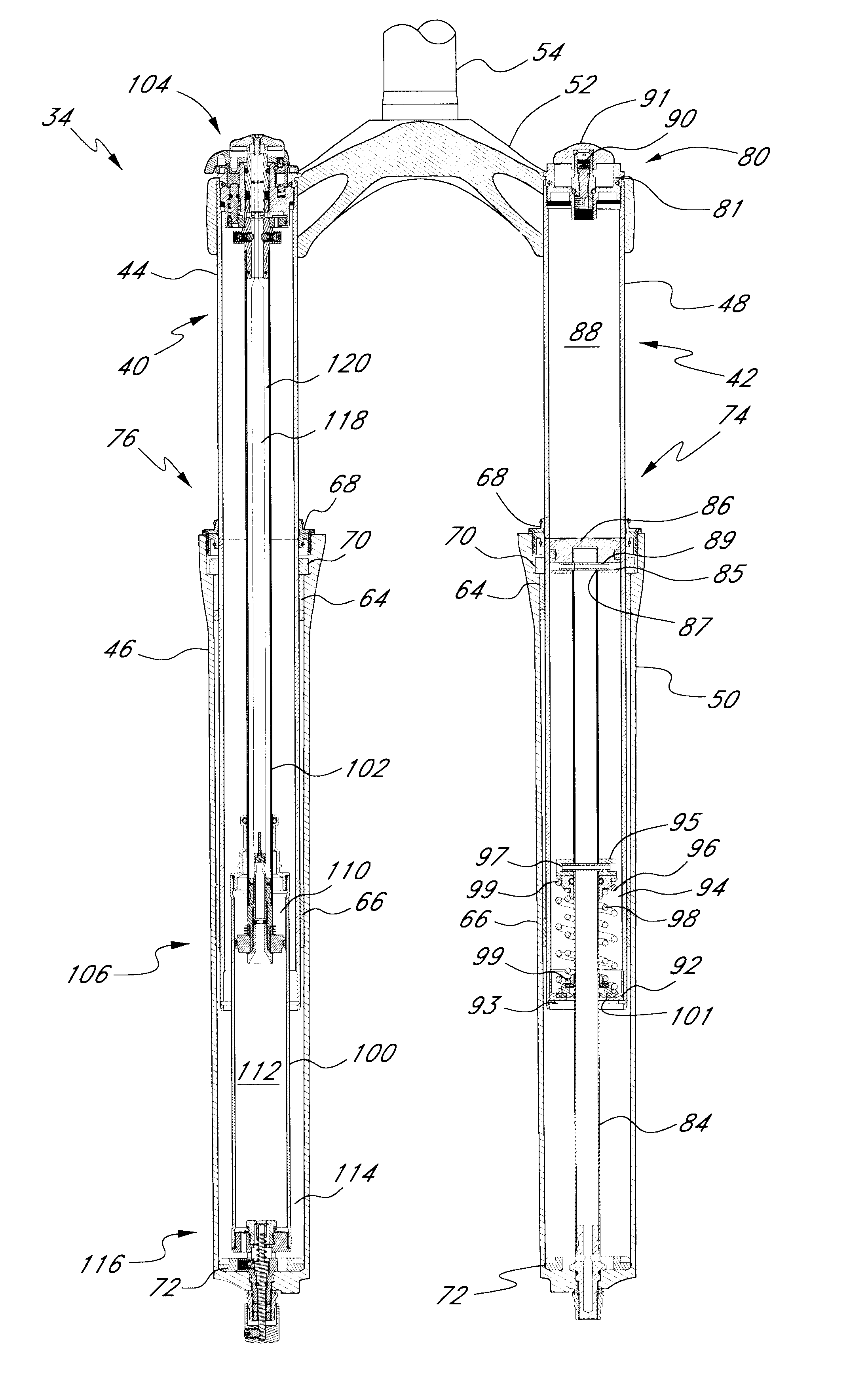
FIG. 15 is a cross-section of a coil-sprung embodiment having a coil spring in each leg for providing an expansion force on the fork;

FIG. 16 is a cross-section of the coil-sprung fork of FIG. 15 in a shortened travel position.

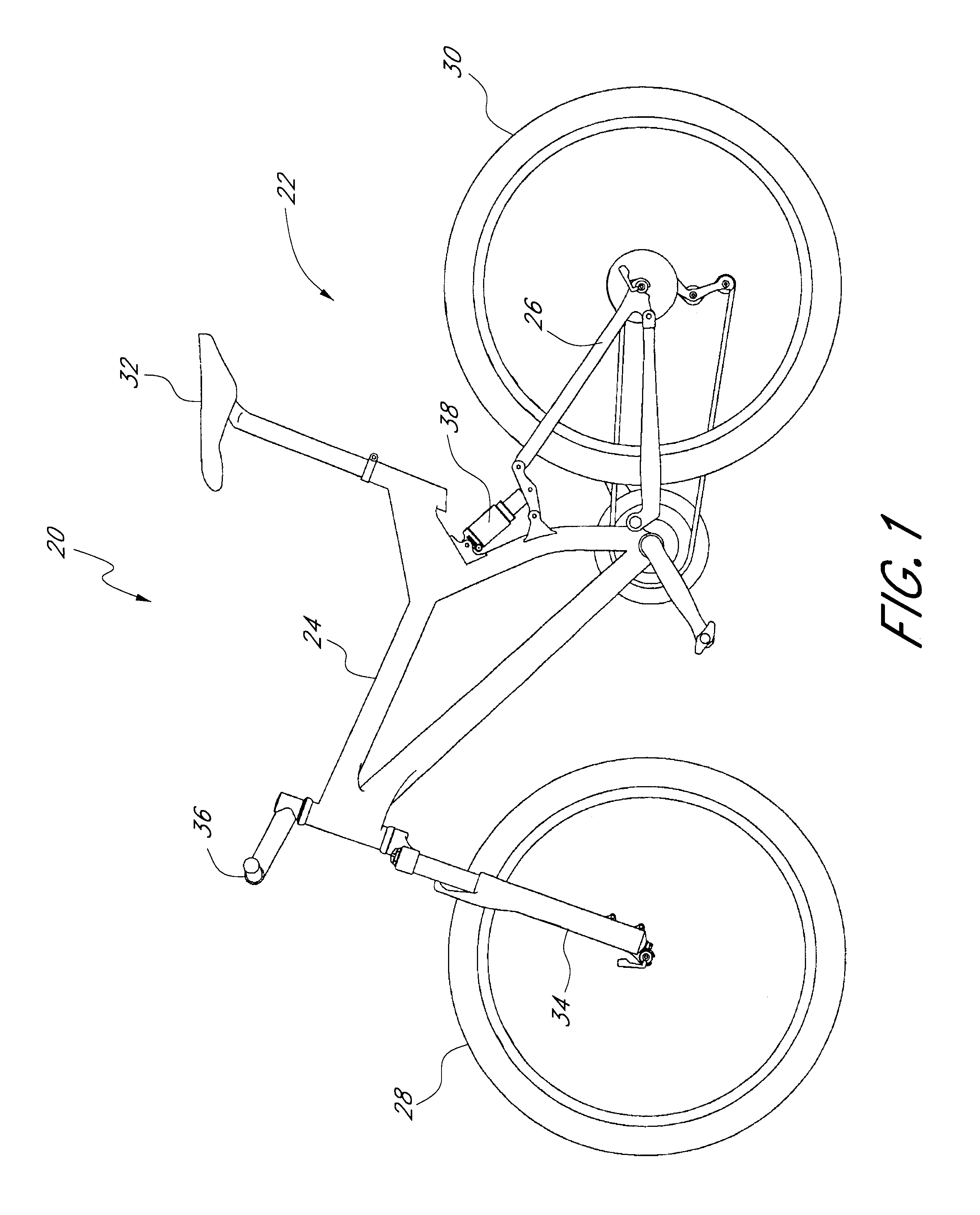
FIG. 1 illustrates an off-road bicycle, or mountain bike 20, including a frame 22 which is comprised of a main frame portion 24 and a swing arm portion 26. The swing arm portion 26 is pivotally attached to the main frame portion 24. The bicycle 20 includes front and rear wheels 28, 30 connected to the main frame 24. A seat...


PUM


Abstract

An off-road bicycle suspension fork includes a pair of fork leg assemblies, each of the leg assemblies having an upper leg telescopingly engaged with a lower leg. A damping assembly is provided in at least one of the legs and includes a cartridge tube connected to the lower leg and a piston connected to the upper tube by a shaft. The piston is telescopingly engaged with the cartridge tube to define a compression chamber below the piston. A control assembly is located at a top portion of the upper leg and is in communication with the compression chamber via a central passage of the shaft. A reservoir is defined between at least a portion of the lower tube and the cartridge. During compression of the suspension fork, fluid flows from the compression chamber, upward through the central passage of the shaft, through the control assembly and to the reservoir.

Description

1. Field of the InventionThe present invention is generally related to vehicle suspension assemblies. More particularly, the present invention is related to a front suspension fork for use on an off-road bicycle.2. Description of the Related ArtSuspension fork assemblies are often utilized on off-road bicycles, or mountain bikes, to absorb energy imparted to the front wheel by the terrain on which the bicycle is being ridden. The use of a suspension fork allows a rider to traverse rougher terrain, at a greater speed and with less fatigue in comparison to riding a bicycle equipped with a rigid fork. Due to the fact that bicycle riders vary greatly in both weight and riding ability, it is highly desirable that certain performance aspects of the suspension fork, such as compression and rebound damping characteristics, be capable of adjustment to suit a particular individual.To avoid the need to disassemble the fork in order to adjust the suspension settings, it is preferable to locate ...

Claims


Application Information

Patent Timeline
Patent Type & Authority Patents(United States)
IPC IPC(8): B62K25/08B62K25/06F16F9/06
CPCB62K25/08B62K25/286F16F9/064B60G17/08F16F9/34B62K2025/048B62K25/06B62K2025/047F16F9/44F16F9/56F16F9/3221F16F13/007
Inventor BECKER, WILLIAM M.LAMPMAN, BRIAN
Owner FOX FACTORY
Learn More