Internally cooled punch

a technology of internal cooling and punch, which is applied in the field of punches, can solve the problems of contaminating the surface of containers, not providing uniform cooling of punches, and adversely altering punch alignmen

Inactive Publication Date: 2003-07-29
STOLLE MACHINERY
View PDF15 Cites 27 Cited by
  • Summary
  • Abstract
  • Description
  • Claims
  • Application Information

AI Technical Summary

Problems solved by technology

The external cooling fluids may contaminate the container surfaces which would then require post-formation cleaning processes that are costly and may be environmentally undesirable.
The prior art systems are disadvantageous because they do not minimize circumferential direction temperature gradients within the ram and do not provide uniform cooling of the punch.
Circumferential thermal gradients in the ram may distort the ram, adversely altering punch alignment.

Method used


Image

  • Internally cooled punch
  • Internally cooled punch
  • Internally cooled punch

Examples


Embodiment Construction

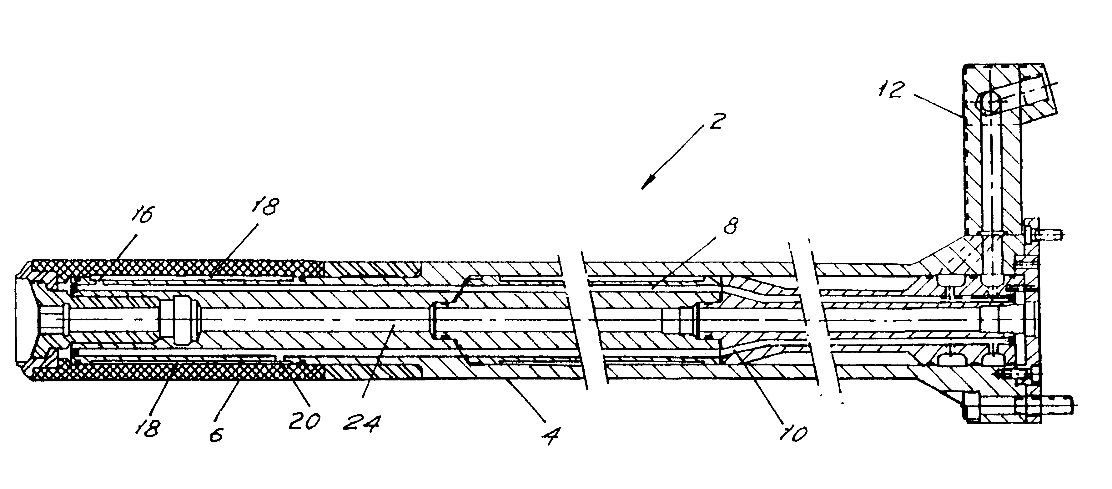
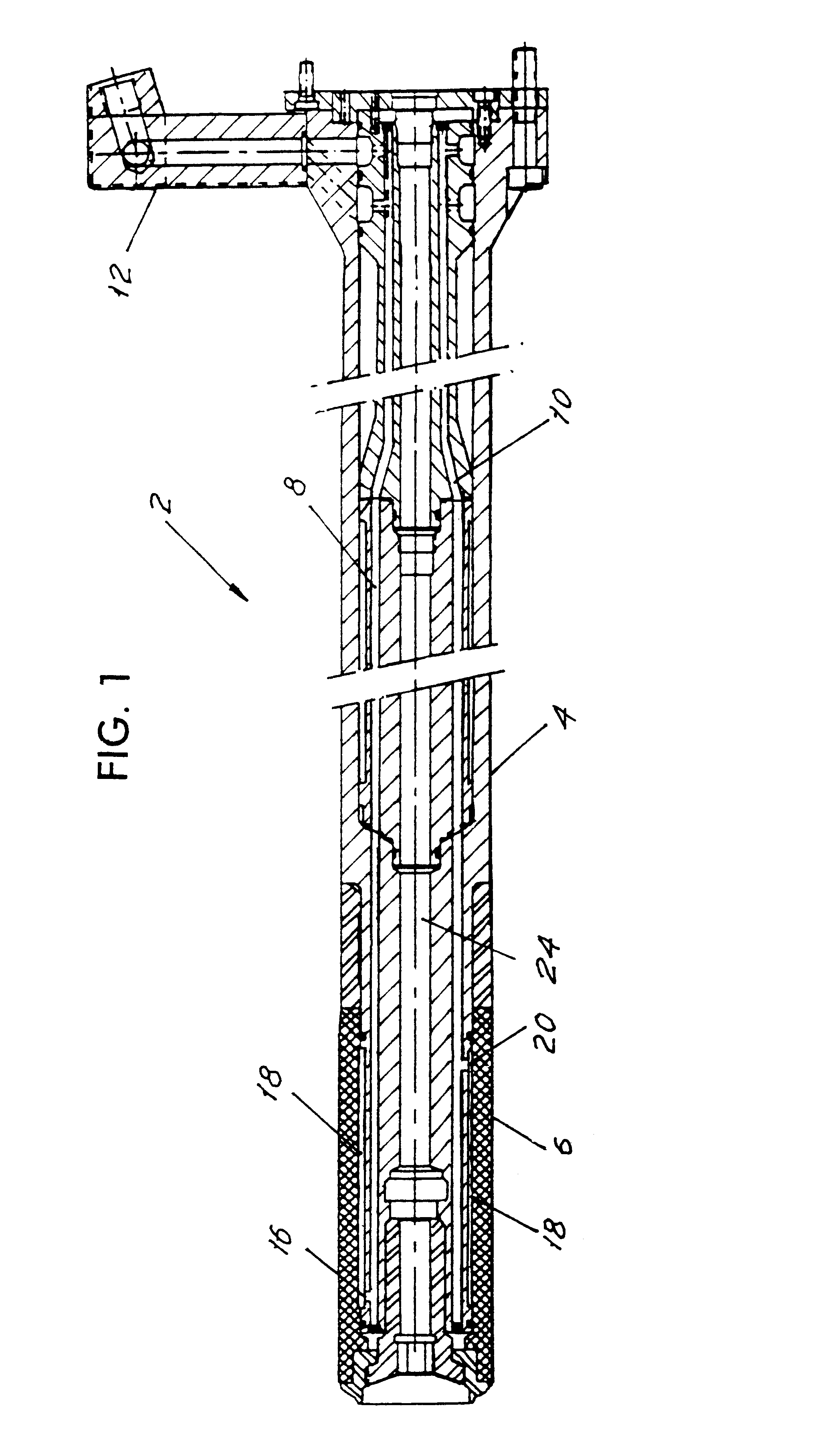
FIG. 1 shows an internally cooled punch assembly 2 according to the present invention in cross section. The assembly includes a reciprocable ram 4 which is conventionally reciprocated through a series of dies (not shown) of a container forming tool assembly (not shown). Such a tool assembly may be seen in a copending application entitled "INTERNALLY COOLED TOOL PACK" and filed herewith. The distal, outer or leading end region of the ram is of narrowed external diameter. A punch 6 is removably disposed on the narrowed distal end region of the ram.

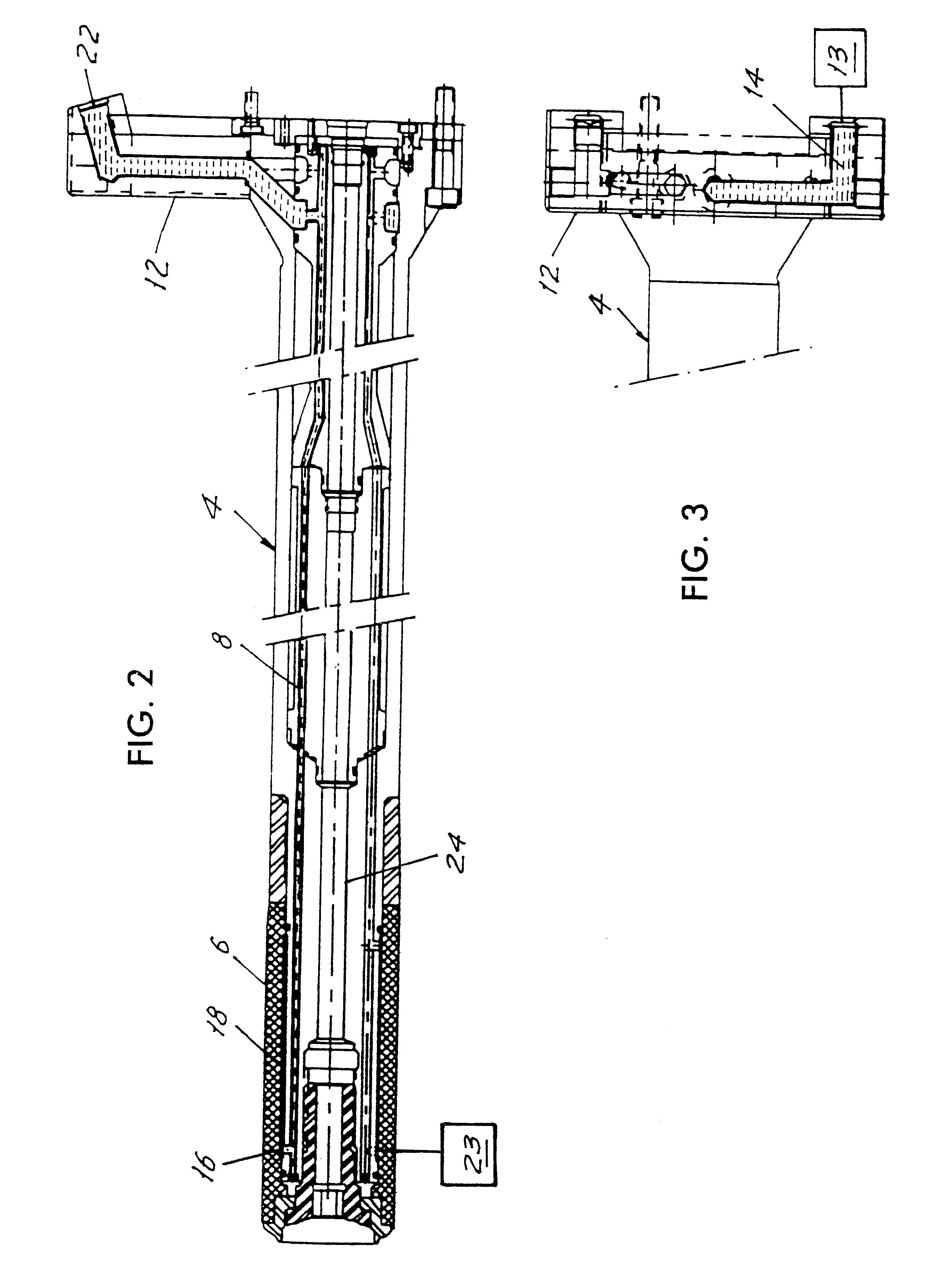
As seen in FIGS. 1 and 5, a plurality of fluid transfer inlet tubes 8 for supplying fluid cooling medium and a plurality of fluid transfer outer tubes 10 for discharging the cooling medium are formed within the ram 4, annularly in a circumferential, symmetrical arrangement, with tubes 8 and 10 alternating. A manifold 12 for connection to a temperature control unit 13 is provided on a proximal end of the punch assembly and connects to at leas...


PUM

PropertyMeasurementUnit
lengthaaaaaaaaaa
temperatureaaaaaaaaaa
thermal transfer propertiesaaaaaaaaaa

Abstract

An internally cooled punch disposed on the end of a ram in a can forming machine. Internal fluid cooling means in the ram avoids the need for externally applied cooling fluids. A plurality of parallel fluid transfer tubes is arranged annularly within the ram. Cooling medium flows through inlet tubes to radial inlet ports which supply the cooling medium to the inner surface of the punch where the medium flows rearwardly through a channel at the inner surface of the punch to radial outlet ports leading to outlet tubes through the ram. Discharged cooling media flows back along the ram and out through a manifold. The transfer tubes are arranged symmetrically in an alternating array circumferentially around the ram to reduce radial temperature gradients within the ram. A central port allows air flow through the ram to aid in stripping the formed container from the punch.

Description

1. Field of the InventionThe present invention relates generally to punches useful in forming cans from cups and particularly for two piece can forming, and more specifically to such punches that are internally cooled.2. Brief Description of the Related ArtForming machines are used to form the bodies of metal containers. A shallow metal cup is driven through a set of annular forming dies by a punch to form the more elongate body of the can, e.g. in a known drawing and ironing process. An example of a conventional can forming machine is shown in U.S. Pat. No. 4,173,882 issued to Lee, Jr. on Nov. 13, 1979, the entire disclosure of which is incorporated herein by reference.A separate punch typically is removably secured on the leading end of a reciprocating ram in a drawing and ironing machine. The punch provides an inner mandrel on which the can is shaped, drawn, and ironed as it passes through successive dies. The temperature of the punch should be controlled against the heat generat...

Claims


Application Information

Patent Timeline
Patent Type & Authority Patents(United States)
IPC IPC(8): B21D22/20B21D22/30B21D51/26B21D22/28B21D24/00B21D37/16B21D45/04
CPCB21D22/30B21D51/26B23Q11/10
Inventor BLUE, RODNEY
Owner STOLLE MACHINERY
Why Eureka
Try Eureka