Three-dimensional object molding apparatus

a three-dimensional object and molding technology, applied in the direction of program control, process and machine control, printing, etc., can solve the problems of time and cost more than necessary, easy for the conventional apparatus to produce a finished 3d, and inability to meet the requirements of production

Inactive Publication Date: 2003-09-02
MINOLTA CO LTD
View PDF11 Cites 61 Cited by
  • Summary
  • Abstract
  • Description
  • Claims
  • Application Information

AI Technical Summary

Benefits of technology

A first object of the present invention is to facilitate short-time low-cost molding by using different materials properly in the surface and interior molding.
A second object of the present invention is to allow short-time low-cost coloring of a three-dimensional molded product.
A third object of the present invention is to facilitate clear reproduction of the color intensity and gradations on a three-dimensional molded product as well as allowing short-time low-cost coloring of the product.

Problems solved by technology

However, the 3D molded product produced by the conventional 3D object molding apparatus or an injection molding / cutting machine is formed only of a single resin material except in special cases such as double molding, and is thus only of a single color.
This consumes time and cost more than necessary.
That is, the production of a 3D molded product having a plurality of colors or any combination color must rely on manual operation after molding since it is not easy for the conventional apparatus to produce a finished 3D molded product for a short time at low cost.
It is, however, impossible for the conventional 3D object molding apparatus 100 to have such a configuration.

Method used


Image

  • Three-dimensional object molding apparatus
  • Three-dimensional object molding apparatus
  • Three-dimensional object molding apparatus

Examples


Embodiment Construction

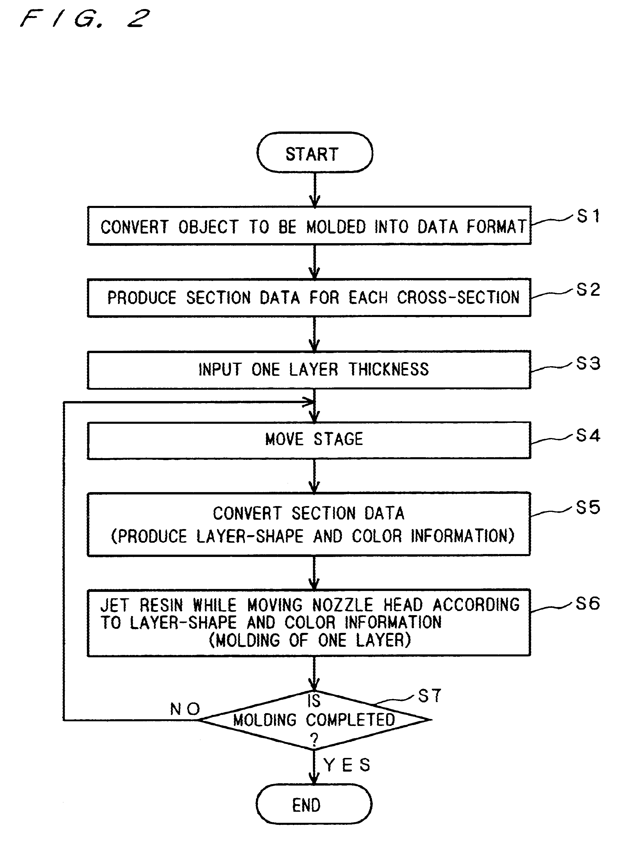
This preferred embodiment gives an example of resins being used as two materials for use in the surface and interior molding. In this preferred embodiment, jets of resins can be controlled separately in the surface and interior molding. By using colored resins as surface materials for use in coloring the surface side of a 3D molded product and an uncolored resin as an interior material for use in molding the interior of the product which is invisible to the outside, molding efficiency can be improved and the consumption of colored resins can be reduced.

We will now describe the first preferred embodiment of the present invention referring to the drawings.

1-1. Whole Structure of 3D Object Molding Apparatus

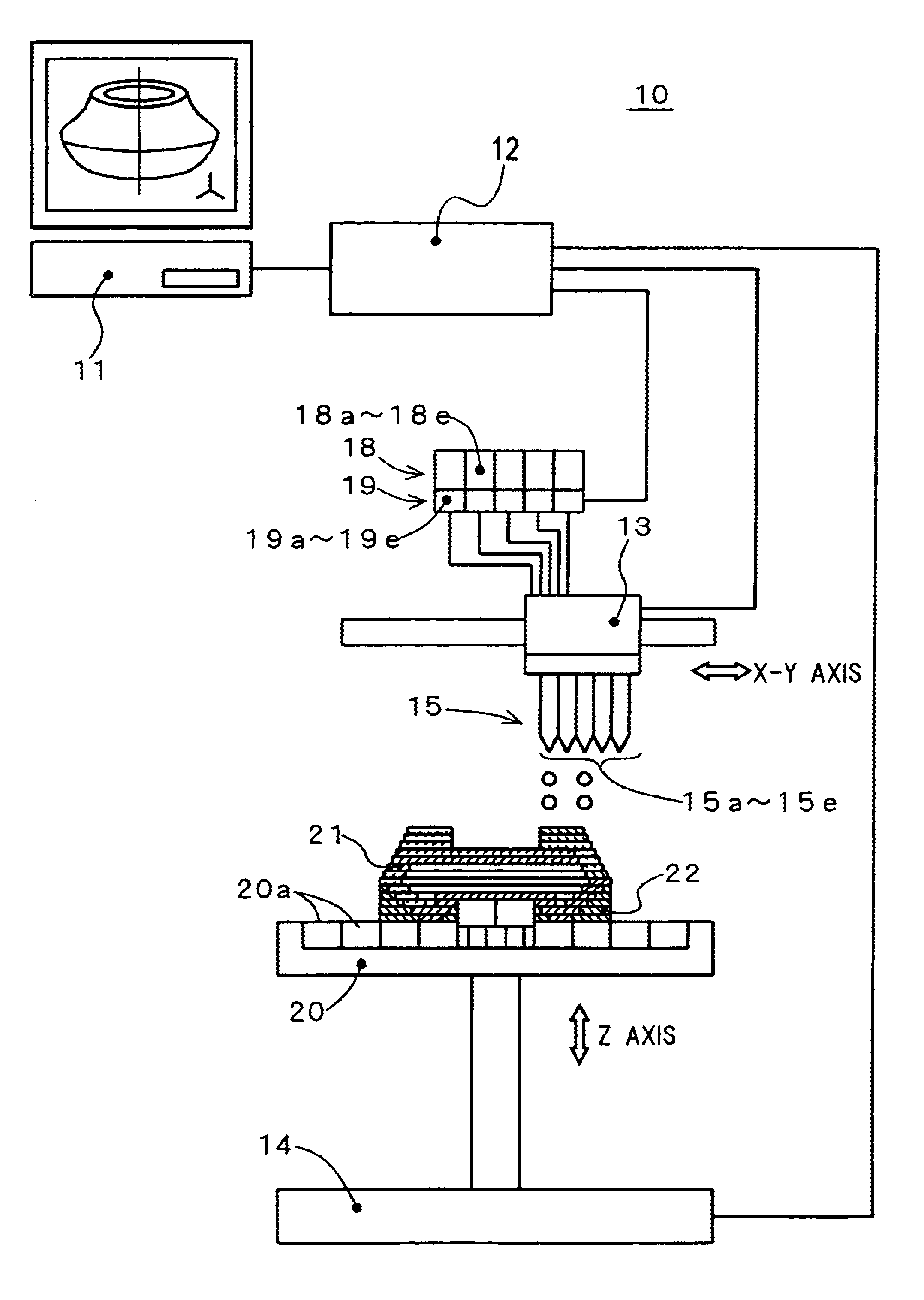
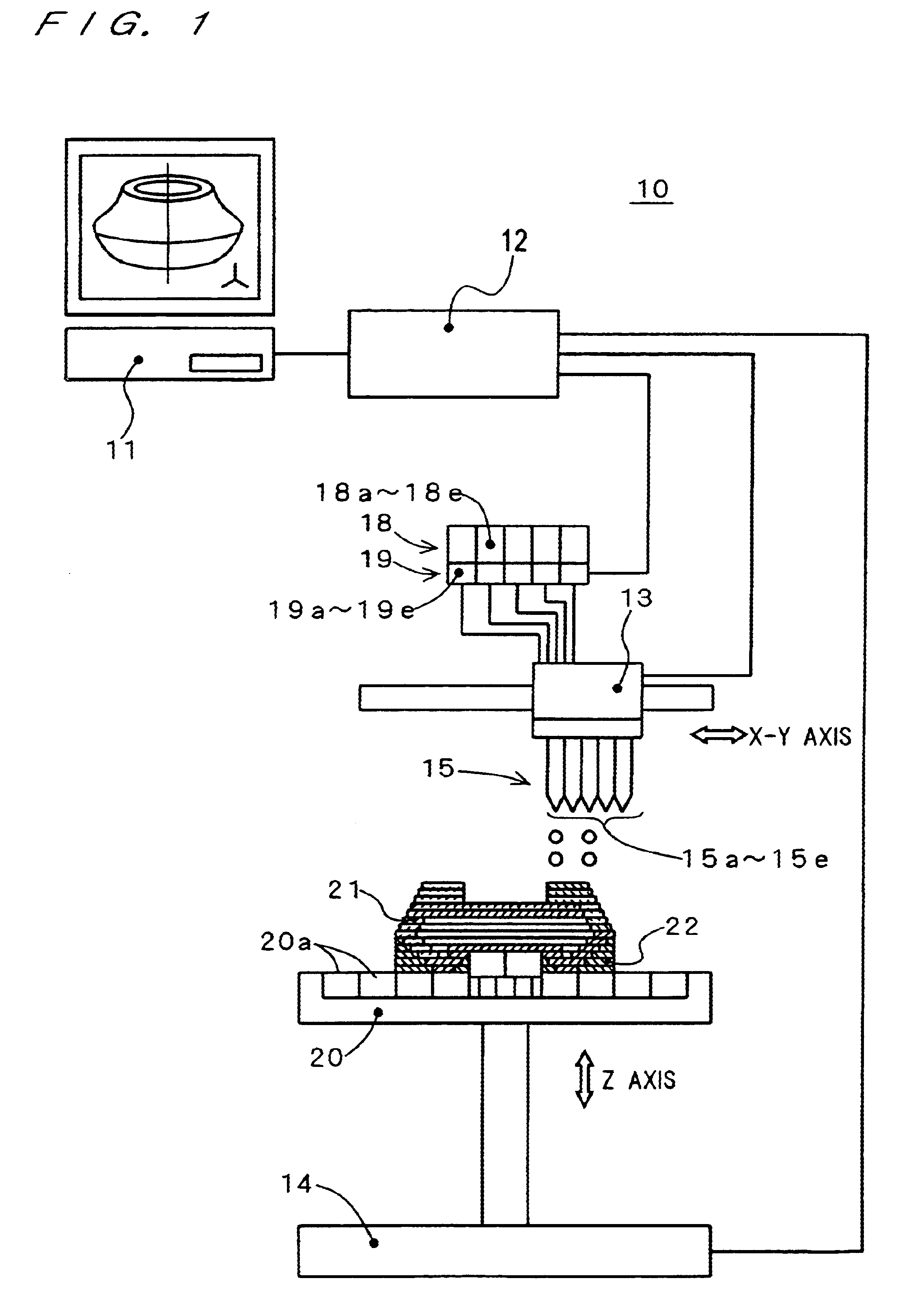
FIG. 1 is a schematic diagram of a 3D object molding apparatus 10 according to this preferred embodiment. The apparatus 10 comprises a computer 11, a drive control unit 12, an XY-directional driving unit 13, a Z-directional driving unit 14, a nozzle head 15, a tank unit 18, a melting...


PUM

PropertyMeasurementUnit
achromatic coloraaaaaaaaaa
chromatic coloraaaaaaaaaa
moldingaaaaaaaaaa

Abstract

A 3D object molding apparatus has a tank holding an uncolored or white resin as a first material for use in molding an interior of a 3D molded object and other thanks holding colored resins as second materials for use in molding a surface of the 3D molded object. A control unit moves a nozzle head in the XY plane and controls jetting of resins from injection nozzles of the nozzle head. When molding an interior of the 3D molded product, at least the first material is jetted and when molding a surface of the product, at least the second material is jetted. The apparatus has coloring nozzles to jet predetermined coloring agents in molding the 3D molded product to achieve coloring of the 3D molded product in the molding process.

Description

This application is based on application Nos. 11-86909, 11-86911, and 11-86912 filed in Japan, the contents of which are hereby incorporated by reference.1. Field of the InventionThe present invention relates to a three-dimensional (3D) object molding apparatus and method especially for manufacturing an intended 3D molded product by jetting materials such as resins in a fluid or liquid state for example in an ink jet system and curing and laminating them in layers.2. Description of the Background ArtConventionally, there have been apparatuses that perform 3D molding of a 3D object by cutting the object at a plurality of parallel planes and successively laminating resins in layers for each cross-section, thereby to produce a molded product or 3D model of the object.FIG. 23 is a schematic diagram of a conventional 3D object molding apparatus 100. In the apparatus 100, a computer 111 converts a 3D object to be molded into a data format and outputs section data which is obtained by slic...

Claims


Application Information

Patent Timeline
Patent Type & Authority Patents(United States)
IPC IPC(8): B29C41/34B29C41/36B29C67/00G05B19/4099
CPCB29C41/36B29C67/0059G05B19/4099B29K2105/0032B29K2995/0021B41M3/001B41M3/16G05B2219/37366G05B2219/49015B29C64/112H04N1/52B33Y10/00
Inventor TOCHIMOTO, SHIGEAKIYAGI, FUMIYAAGAWA, NORIHIROTAKATA, HISASHINORITA, TOSHIO
Owner MINOLTA CO LTD
Why Eureka
Try Eureka