Method of assembling a frame assembly for a partition system

a frame assembly and partition system technology, applied in the direction of floor insulation, floor coverings, roof tools, etc., can solve the problems of low capital investment required for partition system installation, low efficiency of installation, and inability to achieve appropriate tension on fabric, etc., to achieve automatic and uniform tension, improve the overall appearance of the partition system, and effectively receive and support the partition panel

Inactive Publication Date: 2003-09-16
QUANEX HOMESHIELD LLC
View PDF8 Cites 37 Cited by
  • Summary
  • Abstract
  • Description
  • Claims
  • Application Information

AI Technical Summary

Problems solved by technology

For instance, installation of a partition system requires a relatively low capital investment as compared to the capital investment required to construct permanent walls for division of office space.
As understood by those skilled in the art, this manual stretching process is labor-intensive, time-consuming, expensive, and otherwise cumbersome.
Furthermore, because this manual stretching process is inconsistent, the process frequently does not achieve appropriate tension on the fabric.
Ultimately, unacceptable ripples and sags are visible in the fabric covering the partition panel.
The frame component disclosed in the '869 patent to Samarin is particularly deficient in that it is not unitary.
Furthermore, this frame component does not define a cavity to effectively receive and support partition panels that are to be inserted into the frame component for a partition system.
Like the '869 patent to Samarin, the frame component disclosed in the '377 patent to Berman is deficient because it does not define a cavity to effectively receive and support partition panels that are to be inserted into the frame component for a partition system.
The frame component disclosed in the '771 patent to Vipond is also deficient because it does not define a cavity to effectively receive and support partition panels that are to be inserted into the frame component for a partition system.

Method used


Image

  • Method of assembling a frame assembly for a partition system
  • Method of assembling a frame assembly for a partition system
  • Method of assembling a frame assembly for a partition system

Examples


Embodiment Construction

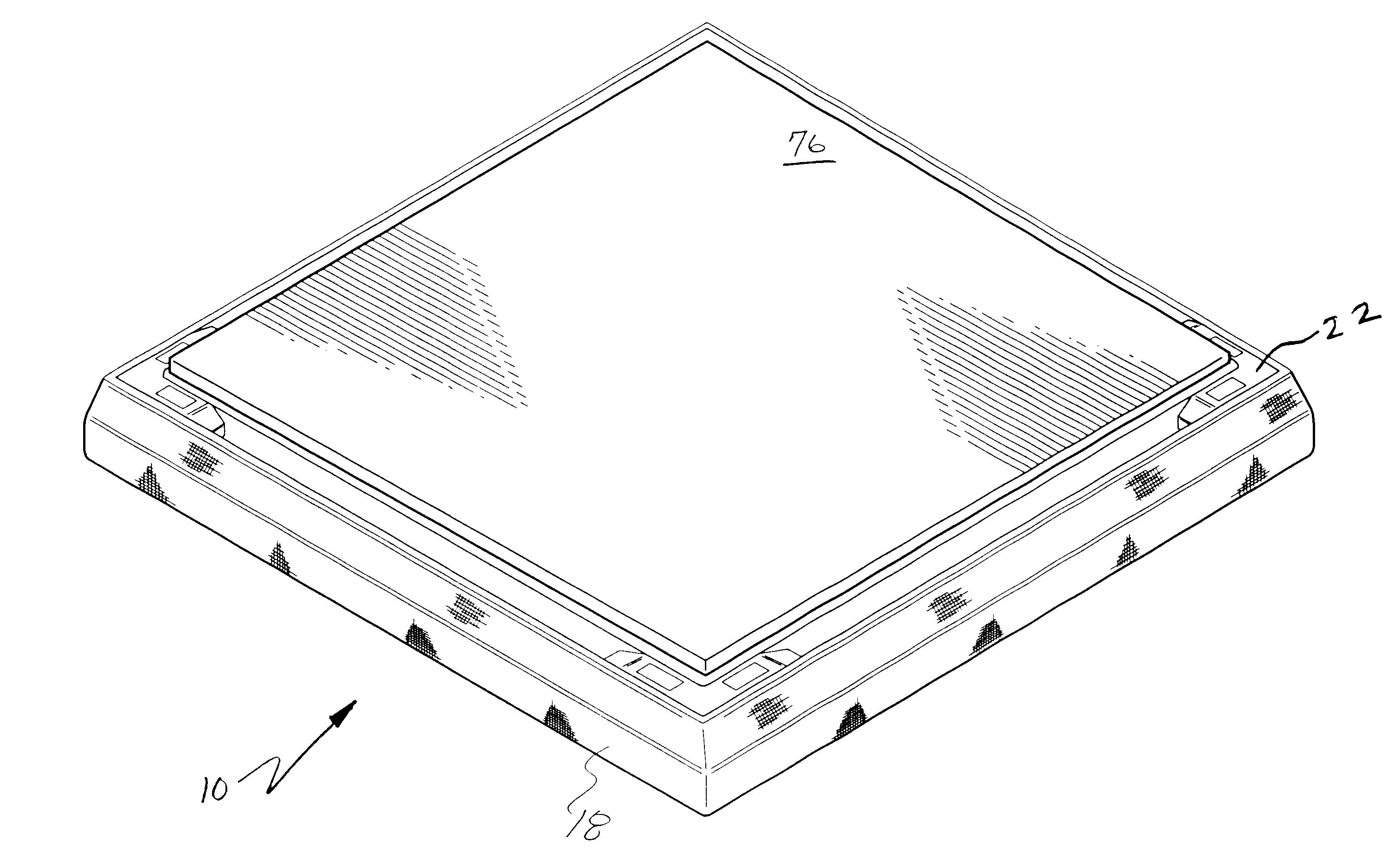
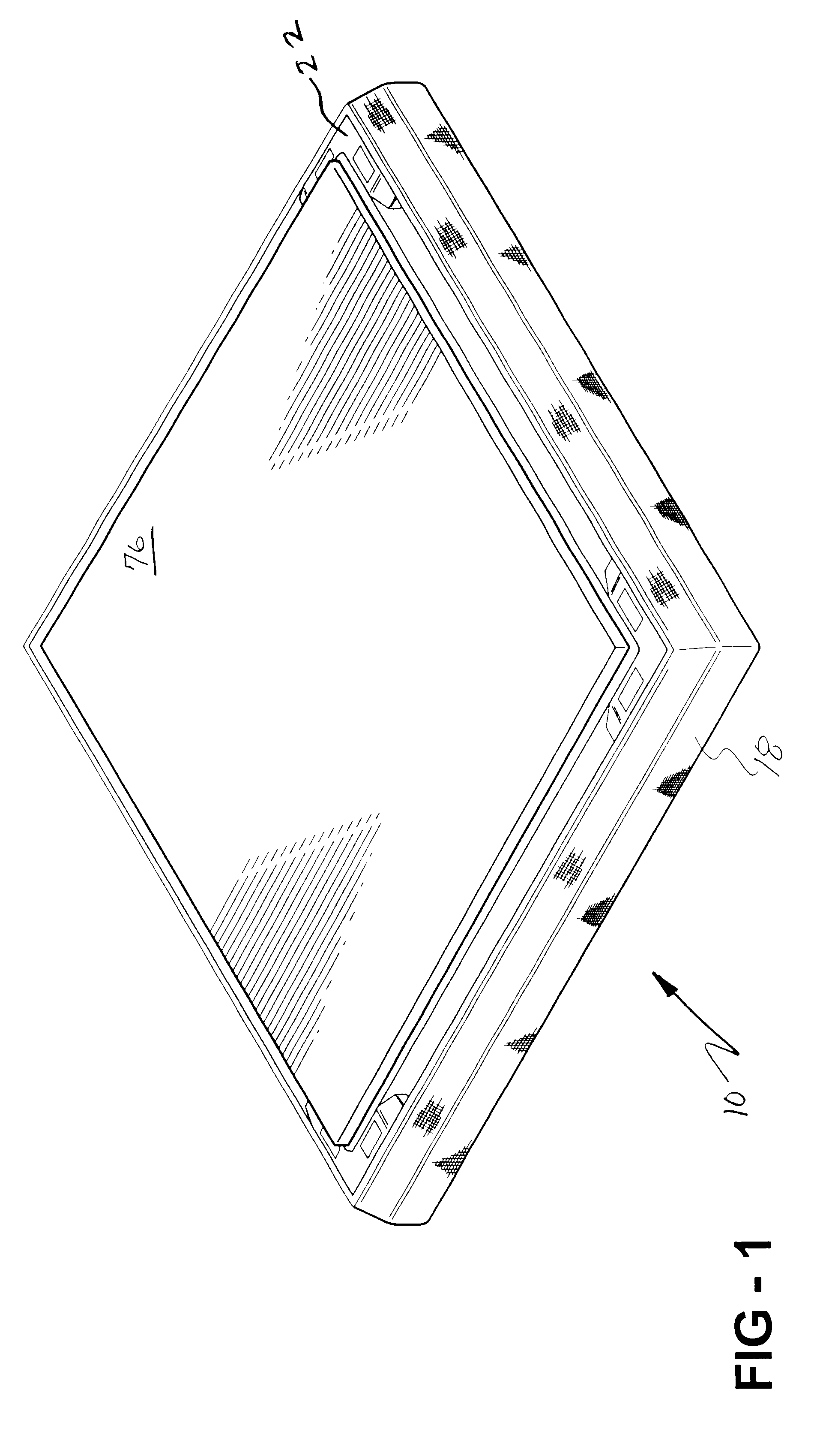
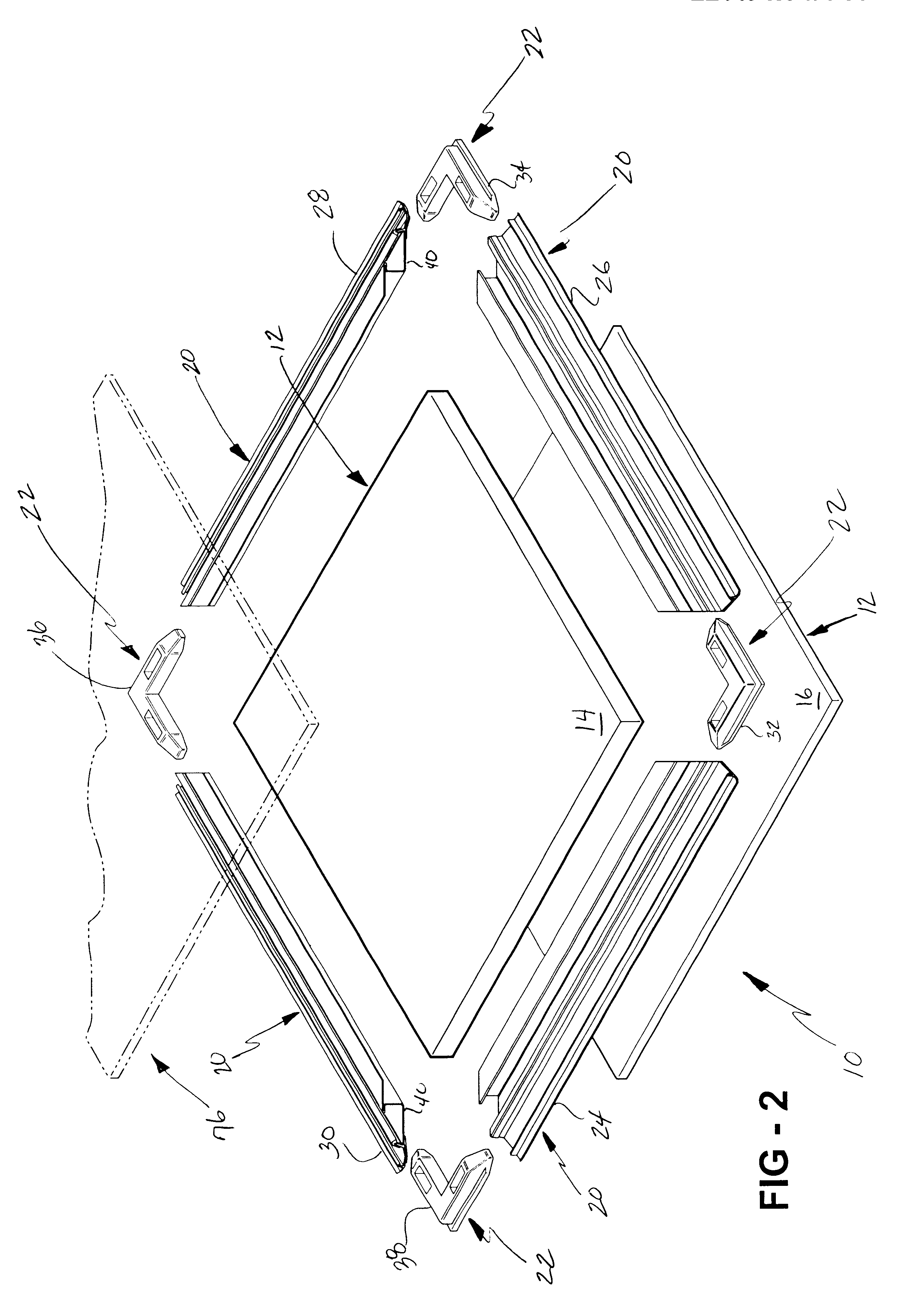
Referring now to the Figures, wherein like numerals indicate like or corresponding parts throughout the several views, a method of assembling a frame assembly, generally shown at 10 throughout the Figures, is disclosed. The frame assembly 10 in the subject invention is for a partition, or cubicle, system. As is apparent from the Figures and from the description set forth below, the frame assembly 10 is assembled in FIGS. 1, 3, and 4, and unassembled in FIG. 2.

The frame assembly 10 includes at least one partition panel 12. In the preferred embodiment, the frame assembly 10 includes a first partition panel 14 and a second partition panel 16. Accordingly, although the frame assembly 10 may include only one partition panel 12, the subject invention is described below in terms of the first and second partition panels 14, 16.

The partition panels 14, 16 can be manufactured from a wide variety of materials. For example, the partition panels 14, 16 can be manufactured from composite or parti...


PUM

PropertyMeasurementUnit
thicknessaaaaaaaaaa
rigidityaaaaaaaaaa
flexibleaaaaaaaaaa

Abstract

A method of assembling a frame assembly for a partition system is disclosed. The frame assembly includes a partition panel, a fabric covering the panel, and a frame component. The frame component automatically and evenly tensions the fabric about the panel. The frame component provided according to this method includes a support element, a lockable element, and an integral hinge defined between the support and lockable elements. The support element defines a cavity for receiving and supporting the panel. The lockable element extends from and is moveable relative to the support element. The panel is inserted into the cavity, and the fabric is mounted to the lockable element. Next, the lockable element is moved about the integral hinge such that the fabric mounted to the lockable element is automatically and evenly tensioned about the panel. A backing strip may be mounted to the frame component to protect the fabric from the integral hinge.

Description

1. Technical FieldThe subject invention generally relates to a method of assembling a frame assembly for a partition, or cubicle, system for dividing office space, building space, and the like. More specifically, the subject invention relates to a method of assembling a frame assembly that provides a frame component of the frame assembly and utilizes this frame component to automatically and evenly tension a fabric about a partition panel of the frame assembly.2. Description of the Related ArtPartition systems and methods of assembling frame assemblies for the partition systems are known in the art. Partition systems are primarily made up of a plurality of partition panels that are interconnected upon installation of the partition system. The frame assemblies for use in the partition systems may also include frame components to border, or frame, the partition panels. The partition panels of the partition systems are utilized to divide office space between co-workers and others to en...

Claims


Application Information

Patent Timeline
Patent Type & Authority Patents(United States)
IPC IPC(8): G09F15/00E04F19/02E04F13/00E04B2/74
CPCG09F15/0012G09F15/0025E04B2002/7479E04F13/00E04F19/02Y10T29/49616Y10S135/913Y10T29/49915Y10T29/49629Y10T29/49904Y10S135/907
Inventor VON ARX, JOHN PAULLIBRANDE, CHARLES JOSEPH
Owner QUANEX HOMESHIELD LLC
Why Eureka
Try Eureka