Portable speed bump

Inactive Publication Date: 2003-09-23
PMG
View PDF40 Cites 48 Cited by
  • Summary
  • Abstract
  • Description
  • Claims
  • Application Information

AI Technical Summary

Problems solved by technology

The principal disadvantage with conventional speed bumps is that they are permanent structures which are not intended to be moved.
If a new situation should arise wherein a speed bump is needed quickly, it would be impossible for a conventional speed bump to be installed due to the time and materials needed to install such a speed bump.
However, these conventional "portable" speed bumps also have disadvantages associated with them that rendered them impractical to use.
Although the Schafer Patent suggests that the modular speed bump is removable from the highway surface, it requires extra equipment and time to install and remove a plurality of bolts.
Therefore, the modular speed bump is not truly portable and is not easily deployed and retracted.
Furthermore, the modular speed bump can not be stored and transported as an assembled structure, b

Method used


Image

  • Portable speed bump
  • Portable speed bump
  • Portable speed bump

Examples


Embodiment Construction

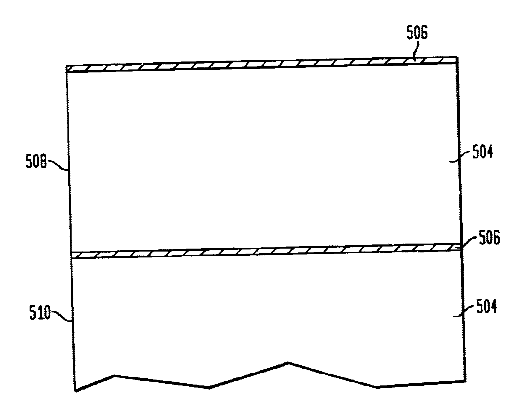
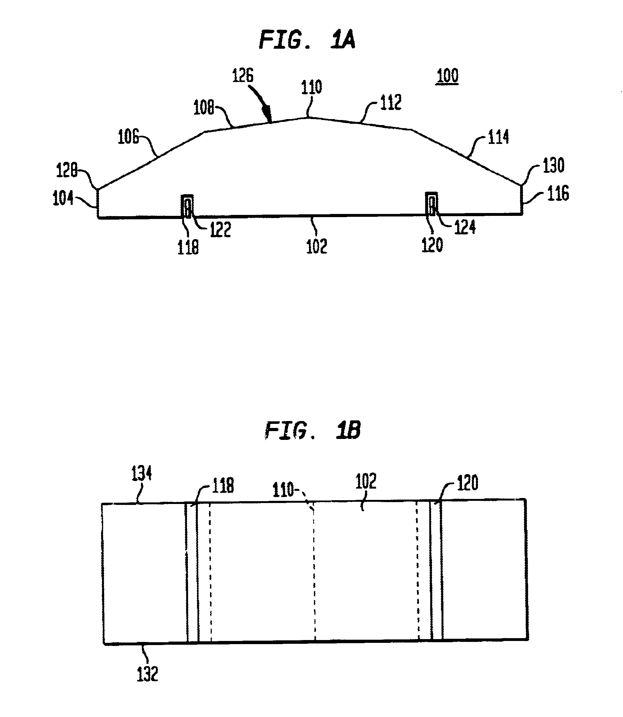
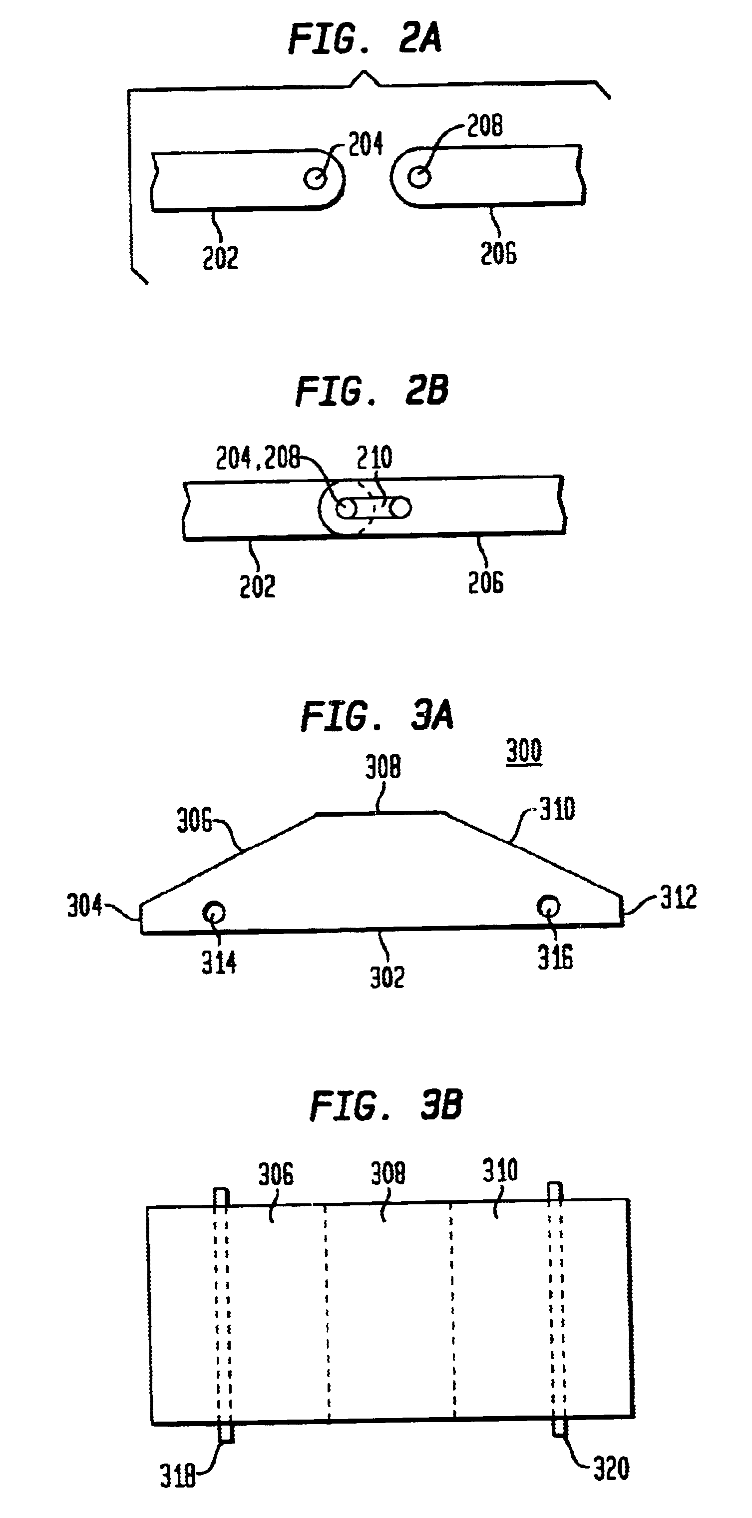
FIG. 1A is a planar view of a cross-section of a portable speed bump (PSB) cell 100 of the present invention, and FIG. 1B is a planar bottom view of the PSB cell 100. In the preferred embodiment, the PSB cell 100 employs a rectangular footprint and has a general trapezoidal cross-section or end profile. Specifically, the PSB cell 100 is a block comprising a bottom 102, a first end 132, a second end 134, a front edge 128, a back edge 130, and a top surface 126, wherein the top surface 126 rises from the front edge 128, to a top point 110 above the bottom 102, and down to the back edge 130, and the first end 132 and the second end 134 are vertical planes extending from the top point 110 down to the bottom 102.

The cross section of the PSB cell 100 can be any shape from a curved, semi-circle (as in a conventional speed bump) to an angled shape. In the preferred embodiment, the top surface 126 of the PSB cell 100 comprises multiple straight edges: a first bottom edge 104, a first lower s...


PUM


Abstract

A portable speed bump unit having a plurality of speed bump cells removably and pivotally connected together to form a single PSB unit of variable length. Each speed bump cell comprises a plastic base having a rectangular footprint, a raised top surface, and a cross-sectional profile that is generally trapezoidal or semi-circular in shape. The speed bump cells are interconnected via one or more hinge bars that are pivotally connected together, thereby allowing two adjacent speed bump cells to be folded together such that an entire PSB unit can be rolled up for easy retrieval, portability, and storage purposes and simply unrolled to an extended position for deployment and use. Alternative embodiments of a portable speed bump unit incorporate safety features, e.g., reflective materials and/or lights, into one or more portable speed bump cells, or a controller into one or more portable speed bump cells for controlling a means for counting vehicles, a means for activating an alarm, or a means for heating the portable speed bump cells.

Description

1. Field of the InventionThis invention relates to apparatuses used to control the speed of vehicles, and specifically, to a portable speed bump for causing a vehicle to slow its speed as it traverses over the portable speed bump.2. Related ArtSpeed bumps are extensively used as an effective means for controlling the speed of a vehicle. They are typically used in those high traffic and / or high populated areas that require slower speeds, e.g., school zones, parking lots, construction zones, tollways, and entrance and exit ramps.The most common speed bump is a permanent structure integrated with a road surface such as an elongated rubber, asphalt, concrete, or steel bars having a rounded top surface. As a vehicle approaches the speed bump, the driver must slow to an appropriate speed in order to prevent severe vibration or jolting of the vehicle when passing over the speed bump. The principal disadvantage with conventional speed bumps is that they are permanent structures which are no...

Claims


Application Information

Patent Timeline
IPC IPC(8): E01F9/014E01F9/04E01F9/047E01F9/011E01F9/529E01F9/70
CPCE01F9/014E01F9/047G08G1/02E01F9/70E01F9/529
Inventor BLAIR, WILLIAM H.BLAIR, DAVID R.STEELE, ROBERT E.
Owner PMG
Why Eureka
Try Eureka