Acoustic touchscreen having waveguided reflector arrays

a waveguided reflector and touchscreen technology, applied in the field of acoustic touchscreens, can solve the problems of undesired weak deflected signals, inability to reduce the width of border regions 15, and the manufacturer of touchscreens not having control over the width of border regions 15

Inactive Publication Date: 2003-10-21
ELO TOUCH SOLUTIONS INC
View PDF8 Cites 115 Cited by
  • Summary
  • Abstract
  • Description
  • Claims
  • Application Information

AI Technical Summary

Problems solved by technology

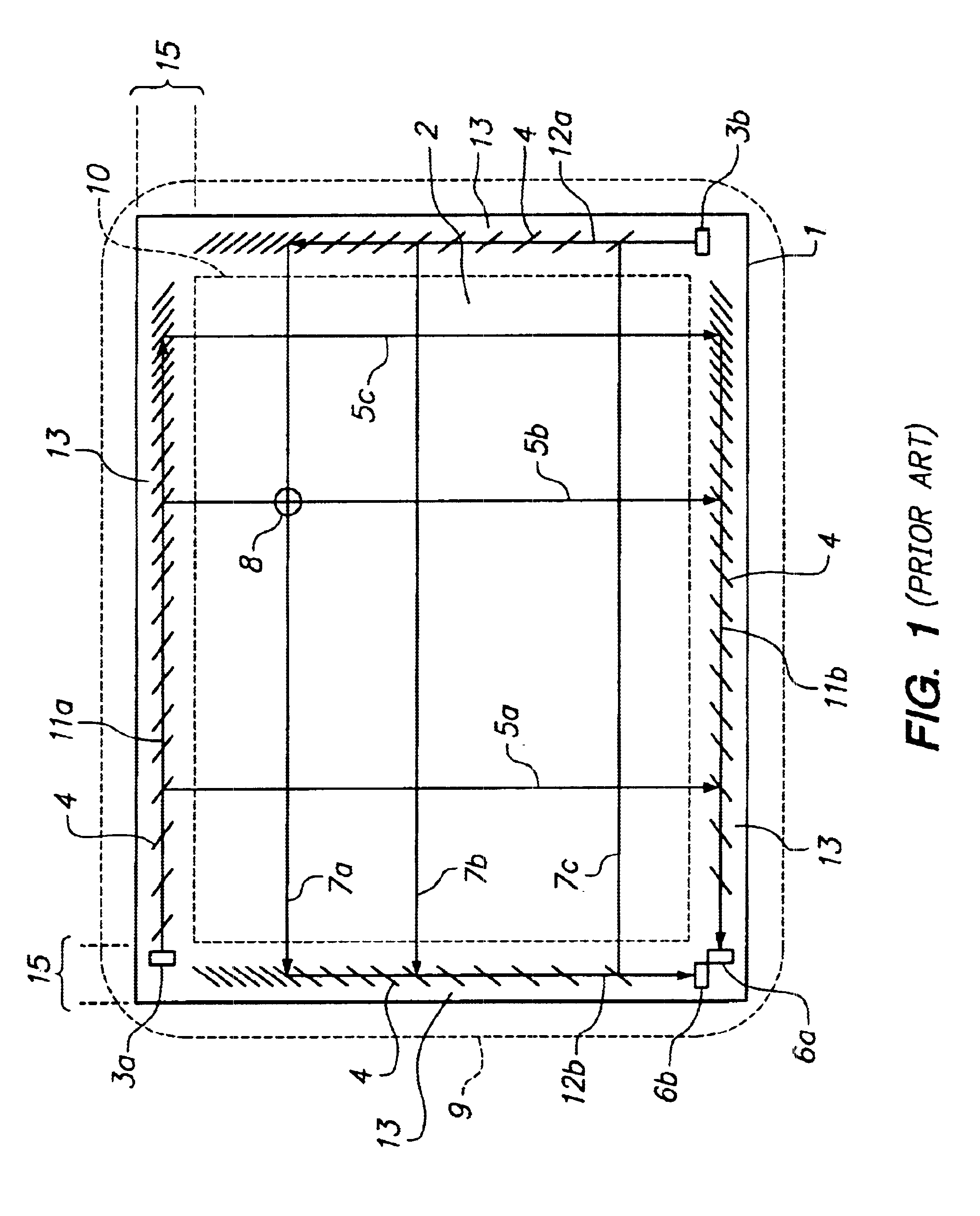
Further, where a touchscreen is constructed directly on the faceplate glass of a CRT, the touchscreen manufacturer may not have control over the width of border regions 15.
However, the widths of these components are not reducible at will.
If the array 13 is too narrow,

Method used


Image

  • Acoustic touchscreen having waveguided reflector arrays
  • Acoustic touchscreen having waveguided reflector arrays
  • Acoustic touchscreen having waveguided reflector arrays

Examples


Embodiment Construction

includes passages that are chiefly or exclusively concerned with particular parts or aspects of the invention. It is to be understood that this is for clarity and convenience, that a particular feature may be relevant in more than just the passage in which it is disclosed, and that the disclosure herein includes all the appropriate combinations of information found in the different passages. Similarly, although the various figures and descriptions herein relate to specific embodiments of the invention, it is to be understood that where a specific feature is disclosed in the context of a particular figure or embodiment, such feature can also be used, to the extent appropriate, in the context of another figure or embodiment, in combination with another feature, or in the invention in general.

Further, while the present invention has been particularly described in terms of certain preferred embodiments, the invention is not limited to such preferred embodiments. Rather, the scope of the...


PUM


Abstract

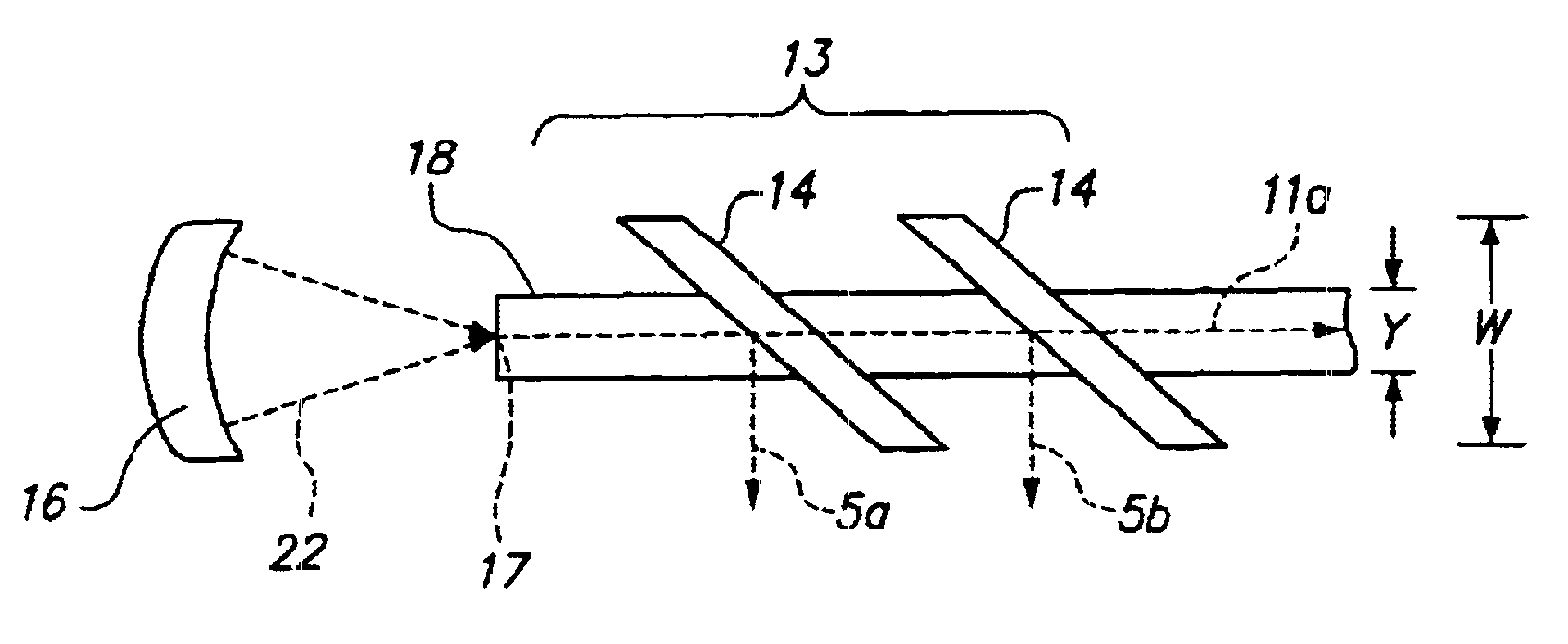
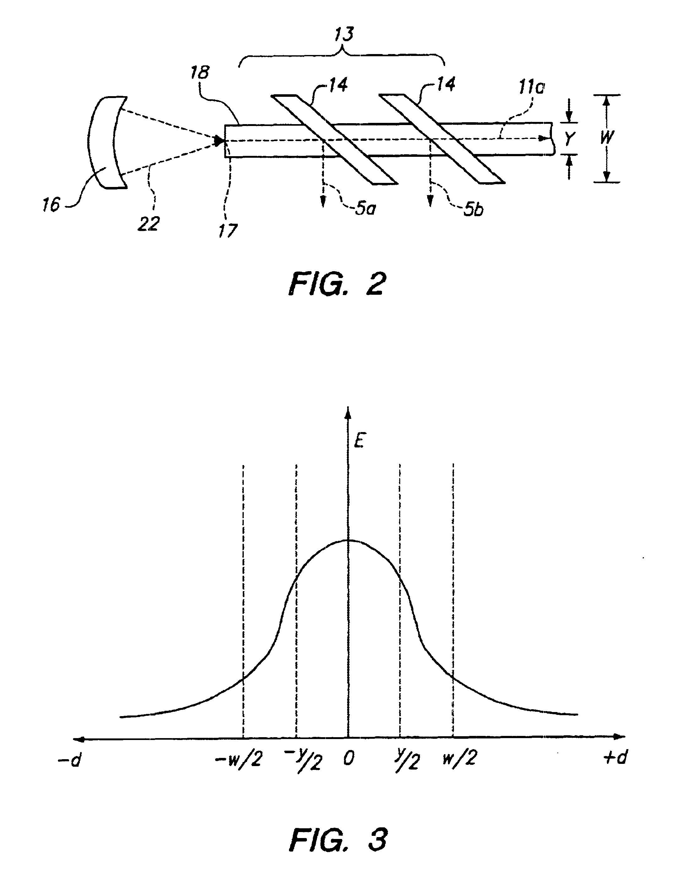
An acoustic touchscreen (1a) has transmitting transducers (23a, 23b) for generating acoustic signals which are deflected across a touch-sensitive area (2) by an array 13 of partially acoustically reflective elements 14. A touch on the touch-sensitive area causes a perturbation in the acoustic signals. After traversing the touch-sensitive area, the acoustic signals are redirected by another array 13 of partially acoustically reflective elements 14, towards receiving transducers (26a, 26b), where the signals (and any perturbations) are sensed. To accommodate touchscreens having narrow border regions (15a), the acoustic signals are propagated across the border regions using acoustic waveguides (18). The waveguide confines the acoustic signals to traveling along a narrow path width, but yet permit them to be deflected across the touch-sensitive area. In this manner, the transducers and reflective elements can in turn be of narrower construction and can fit within narrow border regions.

Description

1. Field of the InventionThe present invention relates to acoustic touchscreens, in particular acoustic touchscreens having narrow reflective arrays and increased touch-sensitive areas.2. Description of Related ArtAn acoustic touchscreen has a touch-sensitive area on which the occurrence and location of a touch is sensed via the touch's effect on the transmission of acoustic waves thereacross. A common type of acoustic touchscreen employs Rayleigh waves (a term which, as used herein, subsumes quasi-Rayleigh waves). Illustrative disclosures relating to Rayleigh wave touchscreens include U.S. Pat. No. 4,642,423 (1987); U.S. Pat. No. 4,645,870 (1987); U.S. Pat. No. 4,700,176 (1987); U.S. Pat. No. 4,746,914 (1988); U.S. Pat. No. 4,791,416 (1988); Re 33,151 (1990); U.S. Pat. No. 4,825,212 (1989); U.S. Pat. No. 4,859,996 (1989); U.S. Pat. No. 4,880,665 (1989); U.S. Pat. No. 4,644,100 (1987); U.S. Pat. No. 5,739,479 (1998); U.S. Pat. No. 5,708,461 (1998) and U.S. Pat. No. 5,854,450 (1998)....

Claims


Application Information

Patent Timeline
IPC IPC(8): G06F3/033G06F3/043
CPCG06F3/0436
Inventor GOMES, PAULO IRULEGUIKENT, JOELAROYAN, JAMES L.KAMBARA, SHIGEKI
Owner ELO TOUCH SOLUTIONS INC
Why Eureka
Try Eureka