Internal weld profile gauge

a weld profile and gauge technology, applied in the field of measuring devices, can solve the problems of impurities entering the system, affecting the quality of welds,

Inactive Publication Date: 2003-10-28
BAREFOOT BYRON G
View PDF15 Cites 15 Cited by
  • Summary
  • Abstract
  • Description
  • Claims
  • Application Information

AI Technical Summary

Problems solved by technology

It is currently theorized that if a weld does not conform to certain tolerances, gas flow over the weld bead will be disturbed potentially resulting in a Venturi effect.
The Venturi effect results in a pressure differential over the weld, which, in turn, causes a moisture buildup at the weld bead.
This moisture buildup will cause corrosion in the pipe thus introducing impurities into the system.
These impurities will reduce semiconductor yield thus causing a reduced manufacturing yield, as well as affecting the integrity of the weld.
The same problems occur when successive pipes along the pipeline are axially misaligned.
However, in order to measure the weld parameters the welder must use complex and cumbersome devices, even using complex mathematical formulas based on the diameter and wall thickness of the pipe.
However, these devices are mechanically cumbersome and require complex calculations or manipulations to arrive at a meaningful result.
Thus, the prior art devices tend to provide irrelevant data to the welder.
Additionally, existing devices are capable of inspecting and verifying only one aspect of the weld bead at a time, thereby requiring the welder to carry multiple cumbersome devices.
Consequently, the welder cannot employ existing devices simply and rapidly.
Similar problems exist with respect to devices for use in verifying axial alignment of pipes, such as the device shown in U.S. Pat. No. 4,255,860 to Ragettli.

Method used


Image

  • Internal weld profile gauge
  • Internal weld profile gauge
  • Internal weld profile gauge

Examples


second embodiment

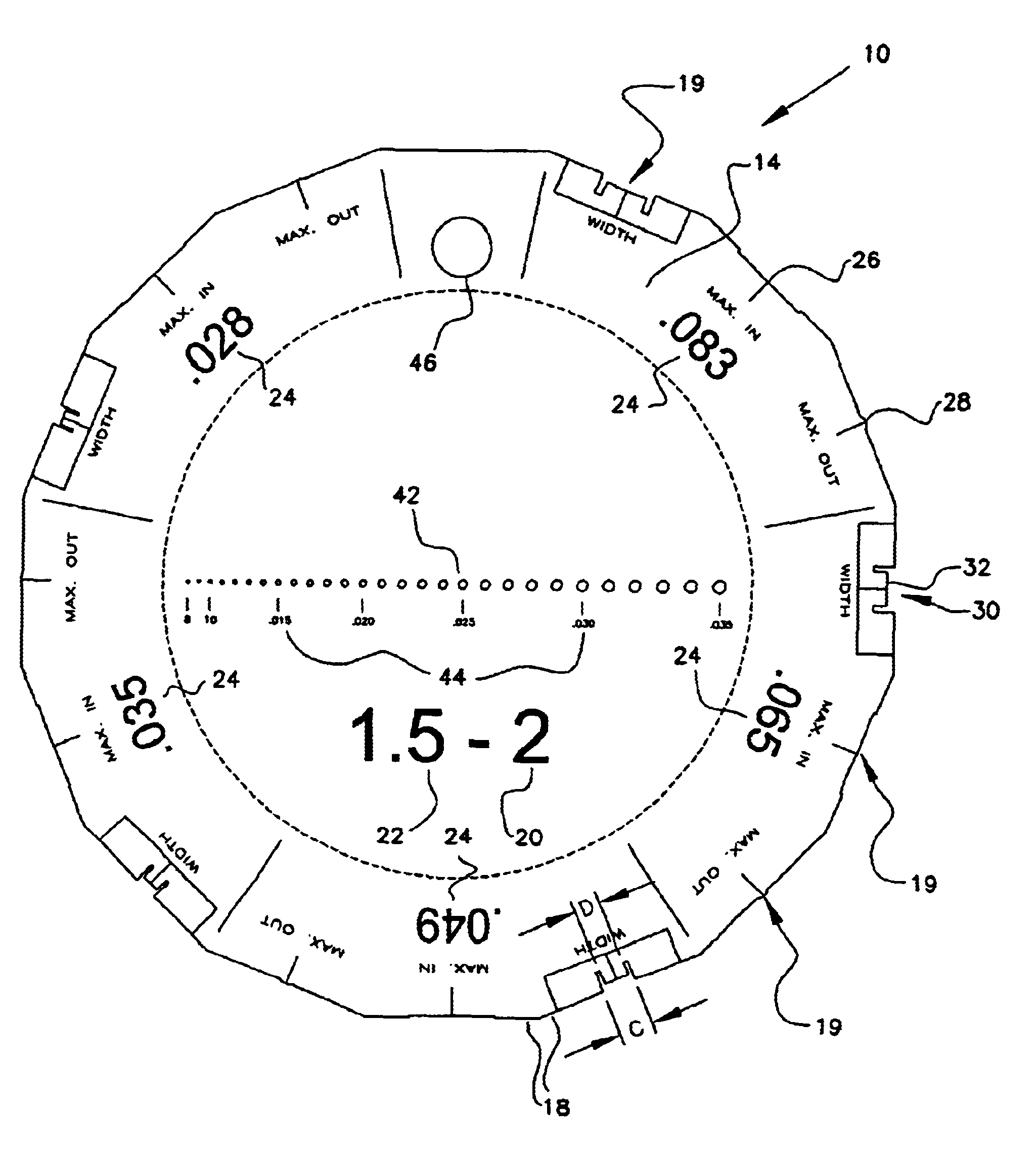
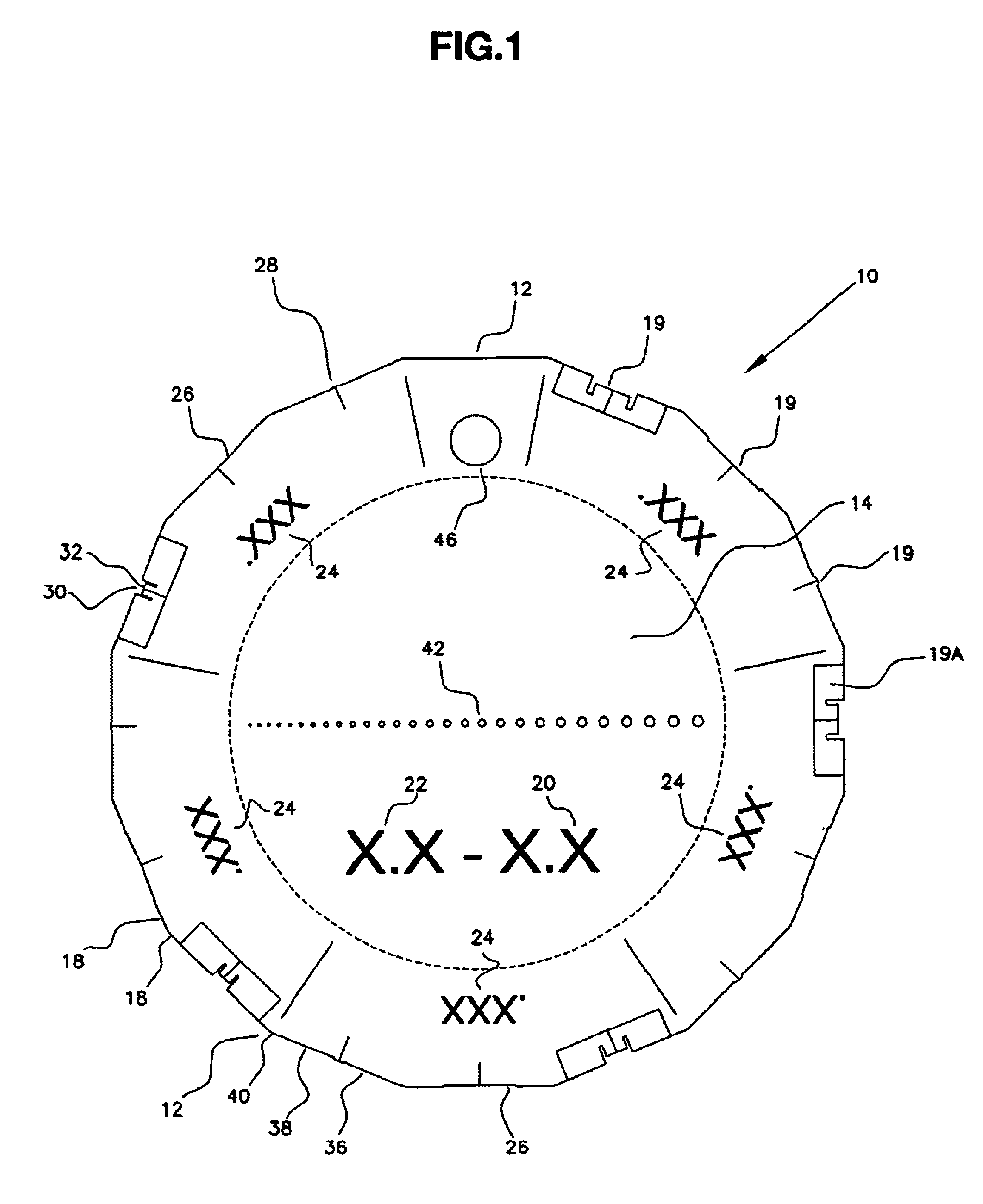
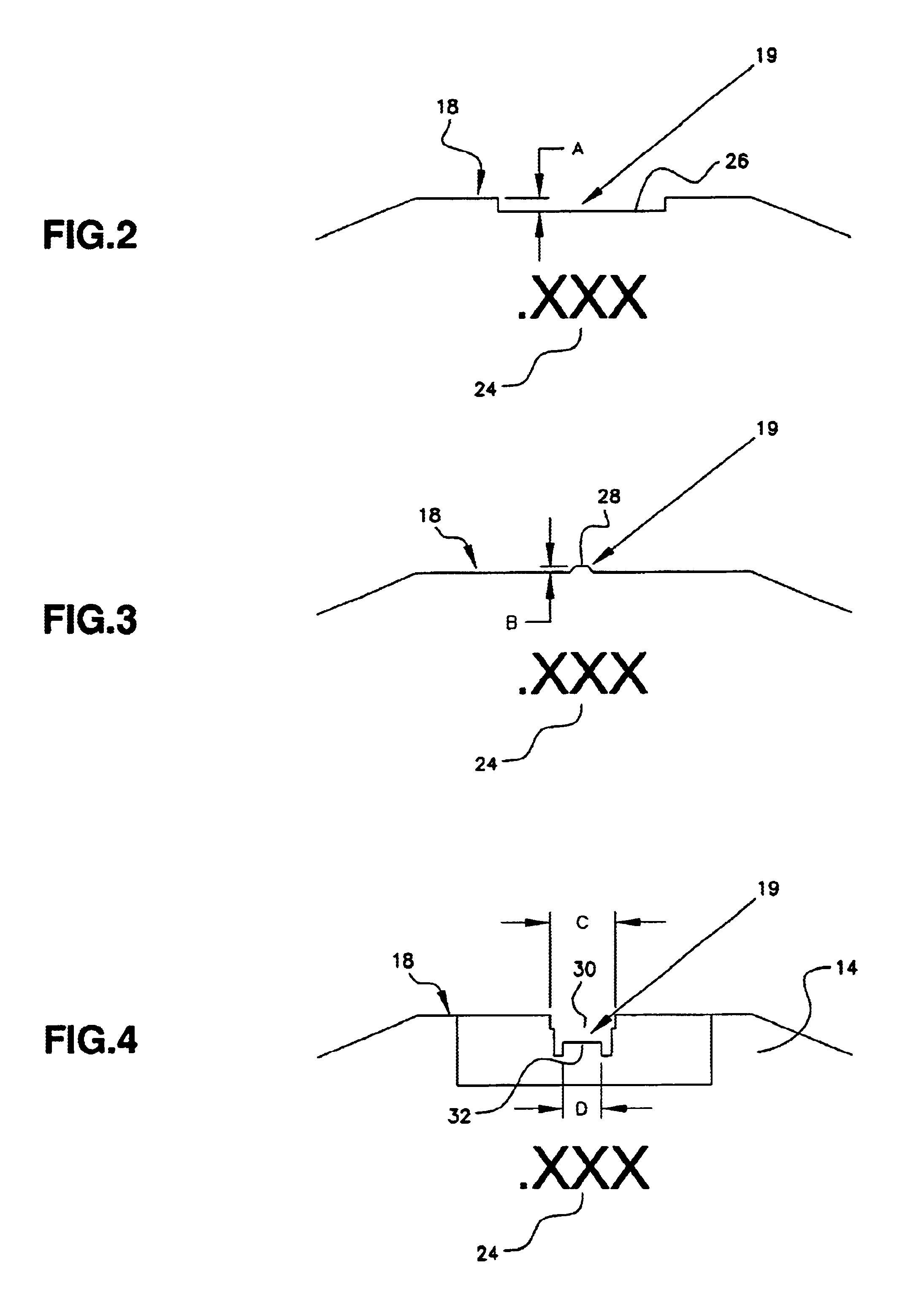
the tool 10, which is substantially similar to the embodiments shown in FIGS. 1 and 6, is shown in FIG. 7. For example, each wall thickness numeral 24 is associated with three fixed measurement structures 19, one of which is a convexity measuring notch 26 as shown in FIG. 2 and described above. A second measurement structure 19 is an axial alignment structure 34, as shown in FIG. 5 and described above. A third measurement structure 19 is used to verify the width of the internal weld bead, including gap 30, tab 32, and a tolerance step 48. This width-measuring structure is shown in exploded view in FIG. 8. As described above with reference to FIG. 4, dimensions "c" and "d" denote the maximum and minimum widths of the internal weld bead, respectively. Step 48 indicates the acceptable variation in the width of the weld bead. Dimension "f" may be a fixed percentage variation from dimensions "c" and "d," associated with a predetermined job site specification, or some other appropriate di...

third embodiment

tool 10 is shown in FIG. 7a. This embodiment is similar to the embodiment shown in FIG. 7, but is for use with only a single wall thickness of pipe as indicated by imprinted wall thickness numeral 24. That is, the embodiment of tool 10 shown in FIG. 7a is adapted to measure maximum bead width, minimum bead width, bead width variation, bead concavity, bead convexity, axial tube alignment for a single pipe wall thickness. Tool 10 may also include holes 42 for measuring tip diameters as described above with reference to FIG. 6. This third embodiment of tool 10 is smaller than the embodiments shown in FIGS. 1 and 7, and accordingly may be used in smaller or more confined spaces.

Method of Use

Selection of the proper tool 10 for a particular inspection is based on the desired ratios of weld bead width to pipe wall thickness, which are indicated by maximum and minimum bead width multipliers 20 and 22 imprinted on surface 14. Selection of the proper edges 18 to use for inspection and verific...


PUM

PropertyMeasurementUnit
thicknessaaaaaaaaaa
thicknessaaaaaaaaaa
thicknessaaaaaaaaaa

Abstract

A tool for inspecting and verifying weld beads in a pipeline includes a plate-like structure which has a surface and edges adapted for inspecting and verifying various weld bead attributes. The surface is imprinted with several identification marks, including for example, wall thicknesses and ratios of weld bead width to wall thickness. The tool can be used to verify weld bead convexity, weld bead concavity, and weld bead width for many different wall thicknesses. The tool is capable of verifying weld bead width and axial alignment of successive sections of pipe along the pipeline. All verifications and measurements are visual and tactile, without need for complex machinery or calculations, and can be accomplished with a single, lightweight tool. Additionally, a single tool can be used to verify weld beads for a variety of different pipe thicknesses.

Description

1. Field of the InventionThe present invention relates generally to a measurement device and, more particularly, to a measuring device for inspecting and verifying weld profiles on a pipe.2. Background DescriptionGas tungsten arc welding is used in many different applications to make welds for piping systems. For example, gas tungsten arc welding is used in clean rooms to make welds on pipelines that supply various fluids and gases to the equipment in the clean rooms. One such clean room is for the manufacturing of semiconductor chips and other similar components.At the present time, many proposed standards are being devised in order to ensure that gas tungsten arc welding meets certain minimum requirements in the clean room and semiconductor environment. These standards will ensure that semiconductor manufacturing applications, for example, operate at peak efficiency. In particular, SEMI.TM. GTA (gas tungsten arc) task force is currently devising weld standards and tolerances for t...

Claims


Application Information

Patent Timeline
Patent Type & Authority Patents(United States)
IPC IPC(8): B23K9/00G01B3/46G01B3/50
CPCB23K9/00G01B3/50B23K31/125
Inventor BAREFOOT, BYRON G.
Owner BAREFOOT BYRON G
Why Eureka
Try Eureka