Chuck device for miniature tool bits

a chuck and tool bit technology, applied in the direction of chucks, mechanical equipment, manufacturing tools, etc., can solve the problem of not being suitable for a miniature tool bi

Inactive Publication Date: 2003-10-28
CHEN TSAI CHING
View PDF7 Cites 125 Cited by
  • Summary
  • Abstract
  • Description
  • Claims
  • Application Information

AI Technical Summary

Benefits of technology

The socket may include an annular shoulder formed between the first and second chambers. The pusher includes a third ring formed thereon for engagement with the annular shoulder, thus avoiding the pusher escaping from the second chamber.

Problems solved by technology

However, such a configuration is not suitable for a miniature tool bit because such an annular groove seriously reduces cross-sectional area and therefore strength of such a miniature tool bit.

Method used


Image

  • Chuck device for miniature tool bits
  • Chuck device for miniature tool bits
  • Chuck device for miniature tool bits

Examples


Embodiment Construction

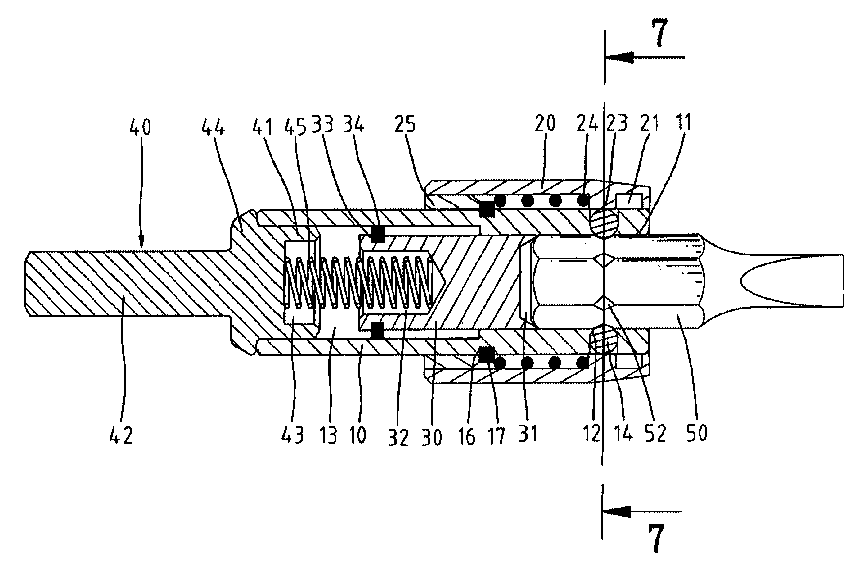
As mentioned, the present invention is related to a chuck device for engagement with miniature tool bits. Therefore, before the chuck device is described, a miniature tool bit 50 is described referring to FIGS. 4 to 8 in view of an ordinary tool bit (not shown). An ordinary tool bit includes a tip and a shank of a hexangular configuration. An annular groove is defined in the shank of the ordinary tool bit for engagement with a ball of a chuck device. Like the ordinary tool bit, the miniature tool bit 50 includes a tip and a shank of a hexangular structure. The shank of the miniature tool bit 50 includes six corners 53. Unlike the ordinary tool bit, no angular groove is defined in the miniature tool bit 50. Instead, a recess 52 is defined in each of the corners 53 of the miniature tool bit 50. At least one of the recesses 52 will be engaged with a ball of a chuck device. The miniature tool bit 50 is formed with such a structure in order not to seriously sacrifice its already small cr...


PUM


Abstract

A chuck device includes a socket, a ball, a first ring, an elastic element, a sleeve, a second ring and a spindle. The socket includes a first chamber defined therein. The first chamber includes a number of slots for receiving the corners. The socket includes a hole defined therein in communication with one of the corner-receiving slots. The ball is received in the hole for engagement with the recess defined in one of the corners of the miniature tool bit. The first ring is formed around the socket. The elastic element is mounted on the socket so as to be compressed between the ring and the annular rib, thus biasing the sleeve. The sleeve includes an annular groove defined in and an annular rib formed on an internal surface thereof. The sleeve is mounted on the socket. The second ring is connected with the sleeve for engagement with the first ring, thus retaining the sleeve on the socket. The spindle is connected with the socket.

Description

BACKGROUND OF INVENTION1. Field of InventionThe present invention relates to a chuck device for engagement with miniature tool bits.2. Related Prior ArtIn both U. S. Pat. Nos. 6,270,085 and 6,325,393, a chuck device is disclosed for engagement with tool bits. As shown in these patents, a tool bit 80 includes a shank and an annular groove 82 defined in the shank for engagement with a ball of the chuck device. However, such a configuration is not suitable for a miniature tool bit because such an annular groove seriously reduces cross-sectional area and therefore strength of such a miniature tool bit. Instead of an angular groove, a recess is defined in each of six corners of such a miniature tool bit. To match such a miniature tool bit, a new chuck device is needed.SUMMARY OF INVENTIONIt is the primary object of the present invention to provide a chuck device for engagement with miniature tool bits each including a number of corners each defining a recess.The chuck device includes a s...

Claims


Application Information

Patent Timeline
Patent Type & Authority Patents(United States)
IPC IPC(8): B25B23/00
CPCB25B15/001B25B23/0035B25B23/0057Y10T279/17752Y10T279/17196Y10T279/17145Y10S279/905
Inventor CHEN, TSAI-CHINGCHANG-KAO, CHIU-MAN
Owner CHEN TSAI CHING
Why Eureka
Try Eureka