Door lock, especially for motor vehicles

a technology for motor vehicles and doors, applied in the field of door locks, can solve the problems of complex manufacturing methods, high actuating forces for lifting the retainer out of the rotary latch, and manufacturing-technological and operating-related disadvantages

Inactive Publication Date: 2003-11-18
HUF HULSBECK & FURST GMBH & CO KG
View PDF9 Cites 37 Cited by
  • Summary
  • Abstract
  • Description
  • Claims
  • Application Information

AI Technical Summary

Problems solved by technology

This door lock has proven to be successful because in the special situation the energy amounts of the motor applied successively in the first and second motor drive phases are transferred simultaneously by the shoulder onto the counter shoulder; however, manufacturing-technological and operating-related disadvantages result.
This requires complex manufacturing methods.
This had the result that the required actuating forces for lifting the retainer out of the rotary latch were high.
Accordingly, the arm on the retainer, which is to receive during release of the force storage device the released lifting force for the retainer, can be very short.

Method used


Image

  • Door lock, especially for motor vehicles
  • Door lock, especially for motor vehicles
  • Door lock, especially for motor vehicles

Examples


Embodiment Construction

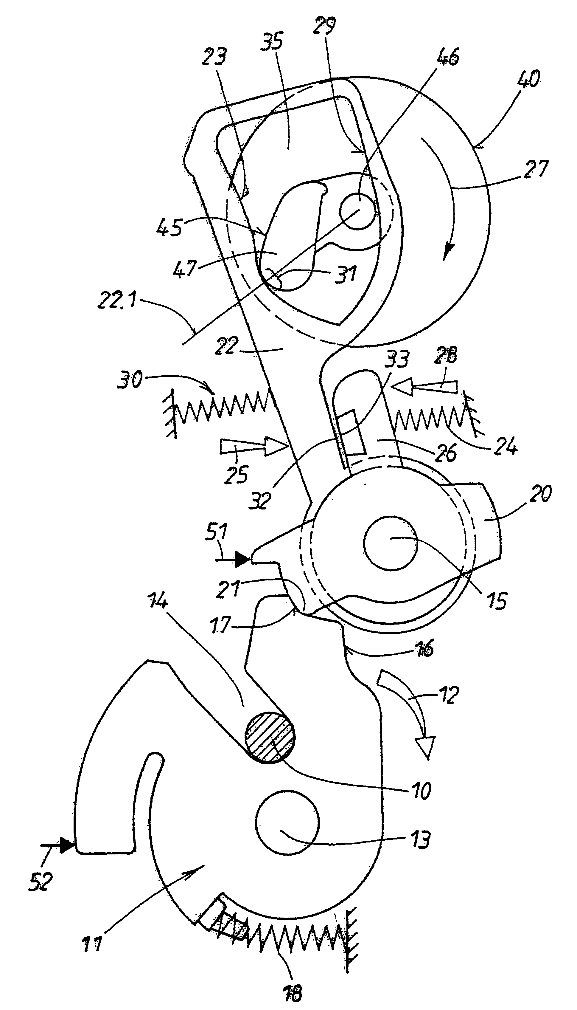
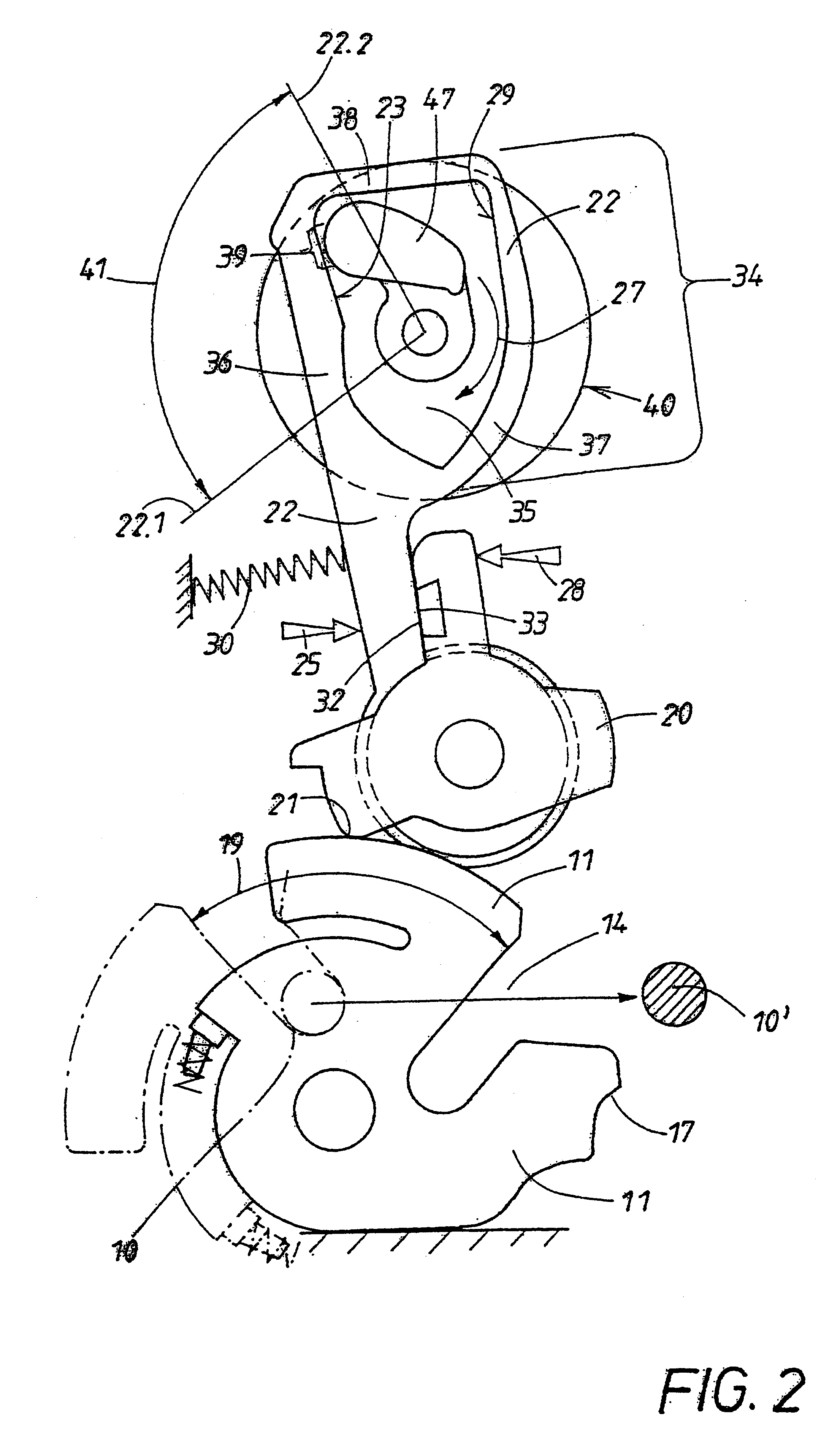
FIG. 1 shows the initial situation in which a rotary latch 11 is locked by a locking arm 21 of a retainer 20 in its locking position. The retainer 20 is loaded in the direction of force arrow 28 by a restoring spring 24. Accordingly, in the illustrated situation the locking arm 21 is secured in the main catch 17 of the rotary latch 11. The rotary latch 11 can also have a pre-latch 16 which engages in a corresponding way the retainer 20. The rotary latch 11 has a receptacle 14 for the locking member 10 which in this embodiment is embodied only as a bolt. The retainer 20 has a fixed fulcrum 15 while the rotary latch 11 is seated on a bearing pin 13. The rotary latch 11 is itself loaded in the direction of arrow 12 by a restoring spring 18 which has the tendency to transfer the rotary latch 11 into an open position illustrated in FIG. 2.

The door lock comprises also a member 22 which is loaded in the direction of arrow 25 by a force storage device 30 and is therefore referred to as "sto...


PUM


Abstract

A rotary latch (11) of a door lock is retained in a detent position by a spring-mounted retainer (20). A motor-driven working member (47) is provided for lifting said retainer (20). An energy-storing device (30) subjects a storing member (22) to a force and hereby serves to lift the retainer (20) out of its detent position in the rotary latch (11). To this end, the storing member (22) has a control surface against which the working member (47) travels in a first motor phase in order to load the energy-storing device (30). A counter-control surface (29) against which the working member (47) travels when lifting the retainer (20) in a staggered second motor phase is also provided. The aim of the invention is to provide a reliable door lock which will also function in the event of an accident. To this end, both the control surface (23) and the counter-control surface (29) are located on the storing member (22). The additional force required for lifting the retainer (20) acts on said retainer indirectly through the storing member (22). As a result, the quantities of energy produced one after the other in the two motor drive phases can be transmitted spontaneously from the shoulder (32) of the storing member (22) to the counter-shoulder (33) of the retainer (20).

Description

1. Field of the InventionThe invention relates to a door lock wherein the rotary latch receives in its one rotary end position, i.e., its locking position, a locking member which drops into a main catch and locks the retainer against its spring-load. In order to transfer the rotary latch into its open position, the retainer is released. For releasing the retainer, a motor-driven working member is used. The motor is activated, in the case of authorized access of the user, when, for example, an actuator belonging to the door lock is directly or indirectly actuated.2. Discussion of Related ArtIn a known door lock of this kind (DE 197 25 416 C1) a force storage device loads the arm of a storing member which is supported on the motor-driven working member and thus defines the charged state of the force storage device. This storing member has a shoulder which, for the purpose of lifting the retainer, impacts against a counter shoulder on an arm of the retainer in order to lift, in the nor...

Claims


Application Information

Patent Timeline
Patent Type & Authority Patents(United States)
IPC IPC(8): E05B65/12B60J5/00E05B65/32
CPCE05B81/14E05B77/06Y10S292/65Y10T292/1082Y10T292/1047
Inventor SZABLEWSKI, PIOTRKIEHL, ERIK
Owner HUF HULSBECK & FURST GMBH & CO KG
Why Eureka
Try Eureka