Articulating joint for an orthopedic brace

a technology for orthopedic braces and articulating joints, which is applied in the field of articulating joints for orthopedic braces, can solve the problems of incompatibility of conventional articulating joints with many existing orthopedic braces

Inactive Publication Date: 2003-12-02
HIPBOLT I P
View PDF14 Cites 44 Cited by
  • Summary
  • Abstract
  • Description
  • Claims
  • Application Information

AI Technical Summary

Problems solved by technology

Thus, conventional articulating joints are not compatible with many of the existing orthopedic braces.

Method used


Image

  • Articulating joint for an orthopedic brace
  • Articulating joint for an orthopedic brace
  • Articulating joint for an orthopedic brace

Examples


Embodiment Construction

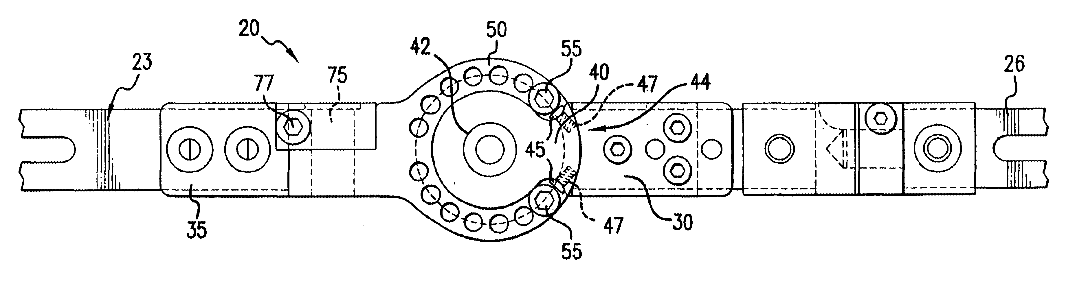
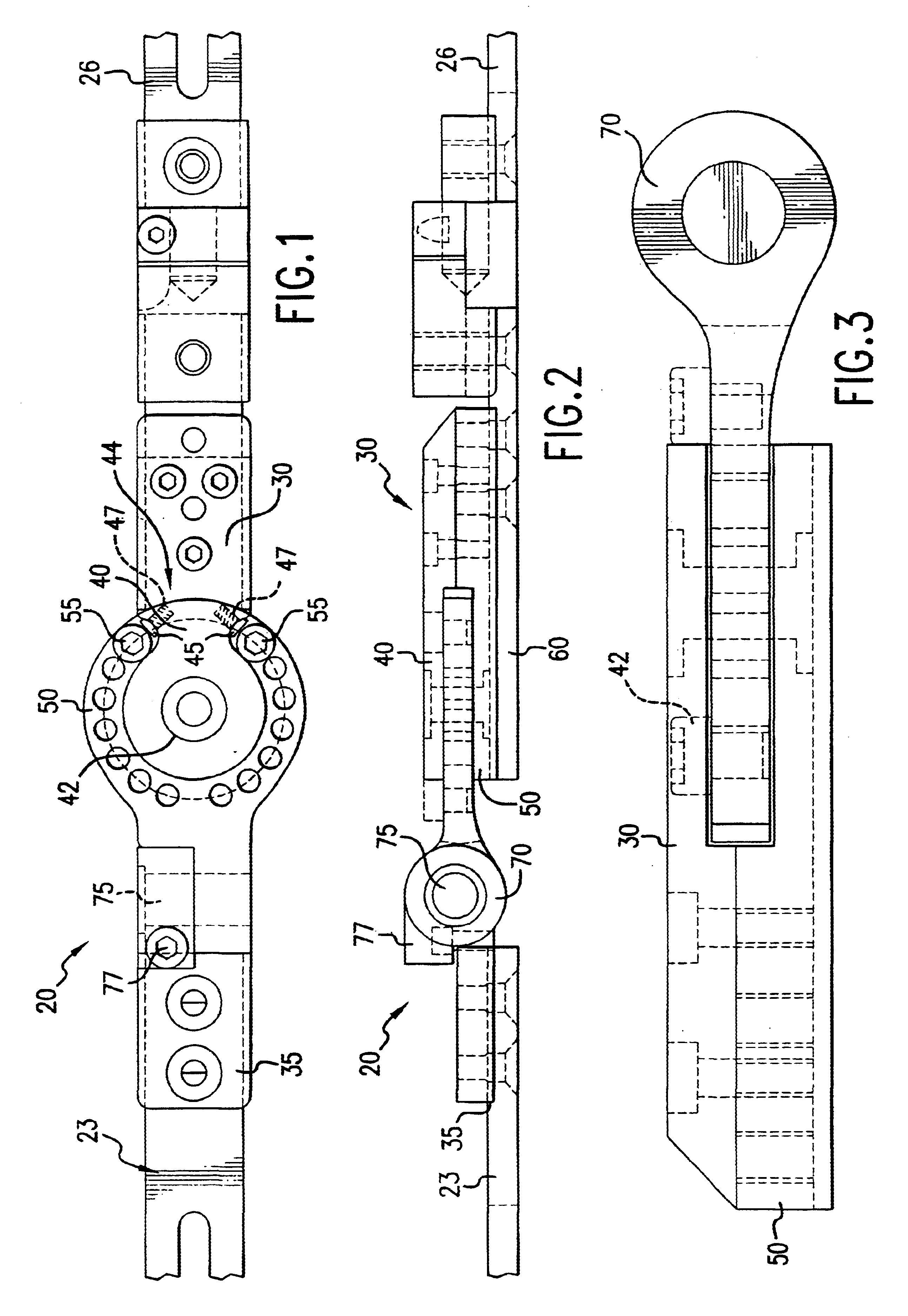
According to one preferred embodiment of this invention, joint 20 is positioned between two struts 23, 26 for limiting the rotational motion between the two struts 23, 26. First strut 23 is preferably attached with respect to one half of an orthopedic brace, such as hip brace 15 and second strut 26 is preferably attached with respect to thigh cuff 18.

As used in the Specification and Claims, the term rotation refers to movement between two specific components and does not generally refer to a medical term of art. The joint according to this invention is designed to permit and / or limit the range of motion of a patient in one or more, and preferably all, planes of movement. Such planes of movement include abduction, adduction, flexion, extension and rotation.

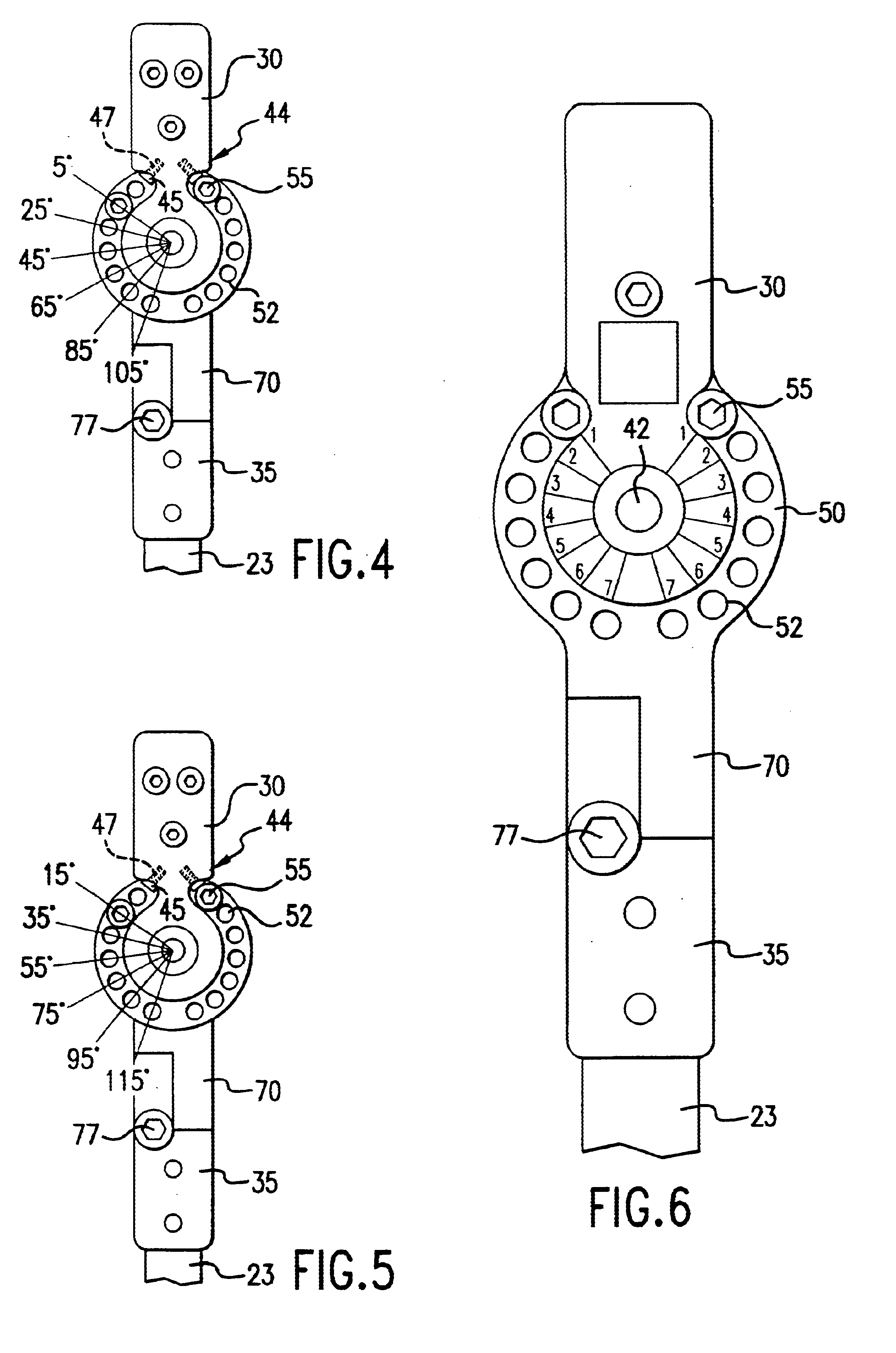
As shown in FIGS. 1-6, joint 20 preferably comprises fixed plate 30 and moveable plate 50. Fixed plate 30 and moveable plate 50 are preferably machined from steel, such as 1045 steel, for rigidity and durability. Due to the stresse...


PUM


Abstract

An articulating joint for an orthopedic brace wherein a moveable plate is rotatably connected with respect to a fixed plate. The moveable plate includes a plurality of adjustment apertures positioned around a first axis of rotation wherein one or more coarse limit screws are positioned within the adjustment apertures to limit the range of motion between the moveable plate and the fixed plate within a predetermined arc of rotation. Fine adjustment means are preferably positioned with respect to the fixed plate and obstruct a range of motion of the coarse limit screws. In addition, interchangeable struts are attached to the moveable plate and/or the fixed plate to facilitate connection to the orthopedic brace and custom sizing wherein at least one of the struts is moveable around a second axis of rotation.

Description

1. Field of the InventionThis invention relates to an articulating joint for an orthopedic brace for use in post-operative rehabilitation and / or to combat the effects of chronic disease. More specifically, this invention relates to an articulating joint that permits adjustment of a fixed arc of rotation for orthopedic braces to provide dependable and predictable movement for a patient.2. Description of Related ArtConventional orthopedic braces, such as pelvic braces and knee braces, generally require an articulating joint to connect a first brace or cuff on one side of the affected joint with a second brace or cuff on the other side of the affected joint. For example, many conventional pelvic braces include a hip brace connected to a thigh cuff. The joint between the hip brace and the thigh cuff traditionally requires a limit to the range of motion or rotation that the patient may exert on the affected joint. As such, an articulating joint should be adjustable between a first point ...

Claims


Application Information

Patent Timeline
Patent Type & Authority Patents(United States)
IPC IPC(8): A61F5/01
CPCA61F5/0125A61F5/0193A61F2005/0134
Inventor COLIGADO, JOSEPH
Owner HIPBOLT I P
Why Eureka
Try Eureka