Method and apparatus for acetabular reconstruction

a technology for acetabular reconstruction and acetabular cup, which is applied in the field of acetabular cup method and apparatus, can solve the problems of increasing the overall hospital cost and inventory control, adding mounting points, increasing surgical time, cost and complexity,

Inactive Publication Date: 2007-11-06
BIOMET MFG CORP
View PDF36 Cites 188 Cited by
  • Summary
  • Abstract
  • Description
  • Claims
  • Application Information

AI Technical Summary

Benefits of technology

[0010]Disclosed is a method and system for trialing an acetabular reconstruction, including a protrusio cage and a trial shell before finally implanting a protrusio cage and a shell. Specifically, a trialing cage can be first trialed in the acetabulum to determine the proper orientation and deflection of the final cage to be implanted. Then a trialing cup may be trialed in the implanted cage to determine the proper orientation of the shell to assure enough clearance around the shell in the cage. The trialing shell can be selectively and removably affixed to the implanted cage to allow a physician to determine whether the shell is in the proper orientation. The shell may then be selectively arranged to allow different orientations of the shell to be trialed before implanting the shell in the cage.

Problems solved by technology

These additional mounting points are generally required due to additional bone loss or defects exhibited at the acetabulum, such as collar / rim defects or pelvic discontinuity defects.
This increased inventory of prosthetic devices increases the overall hospital costs and inventory control.
Furthermore, by requiring the multiple revision acetabular cups to be available during the surgical procedure, multiple prosthetic devices must be sterilized prior to the surgical procedure, thereby increasing the surgical time, cost and complexity.
Because of this two piece system and type of attachment, however, it is often difficult for the surgeon to precisely implant the shell due to the relatively unconstrained possibilities of placing the shell in the protrusio cage.
Moreover, there is not a way of fixing the shell within the protrusio cage before implanting the shell into the cage to test a range of motion of the hip joint after implantation into the shell.
Presently, this is not possible because of the fixation required for the shell into the protrusion cage implant.

Method used


Image

  • Method and apparatus for acetabular reconstruction
  • Method and apparatus for acetabular reconstruction
  • Method and apparatus for acetabular reconstruction

Examples


Embodiment Construction

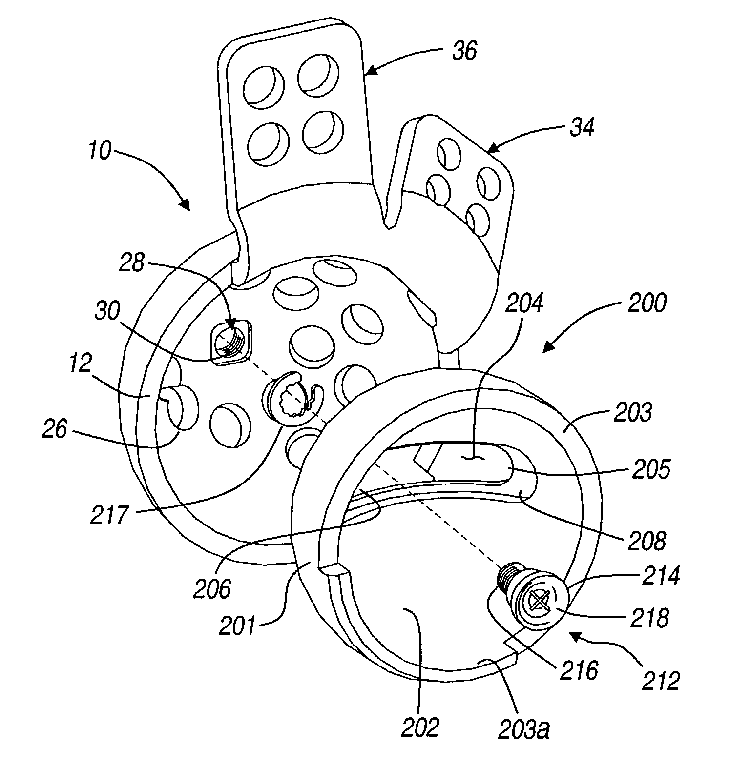
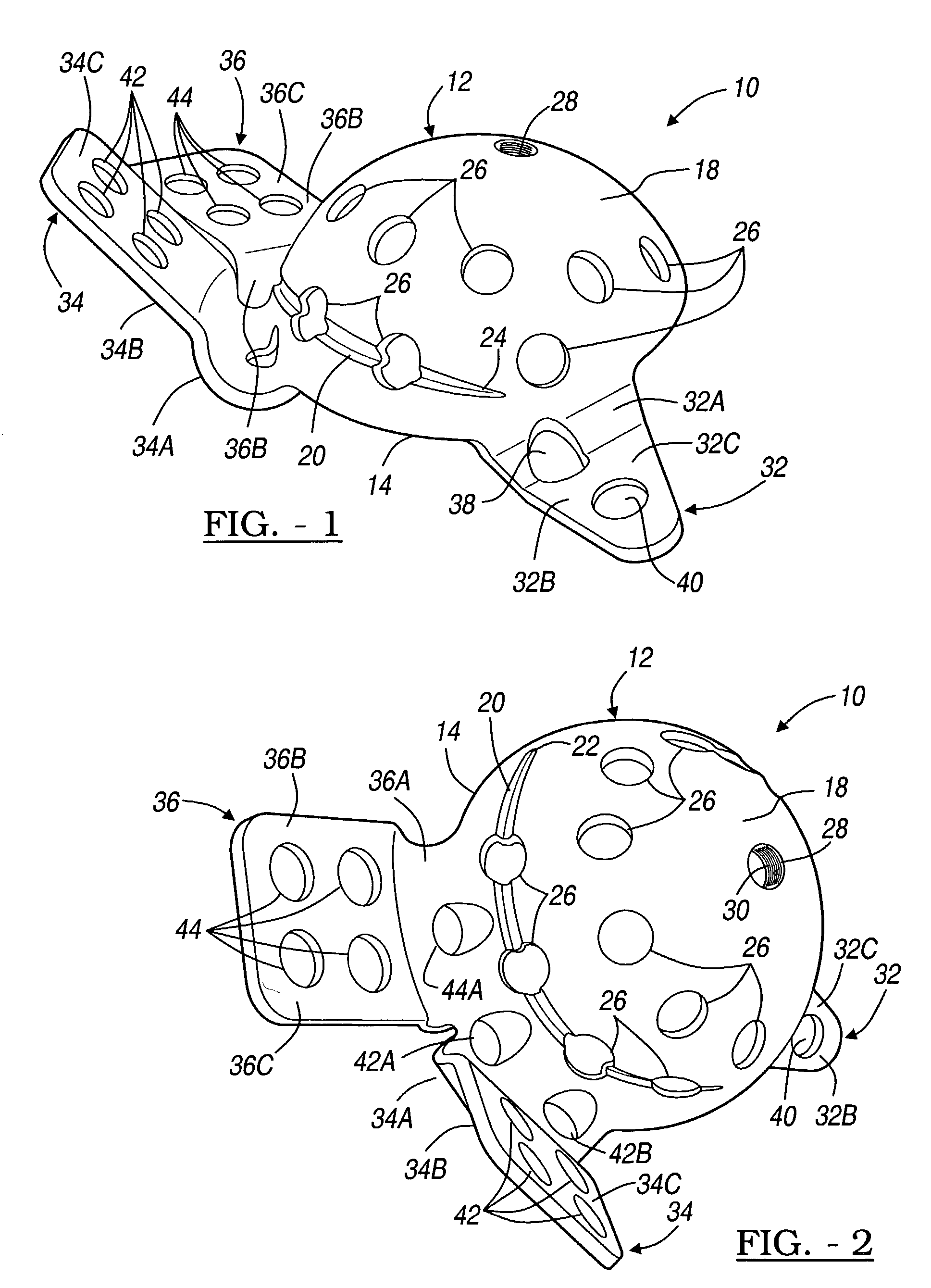
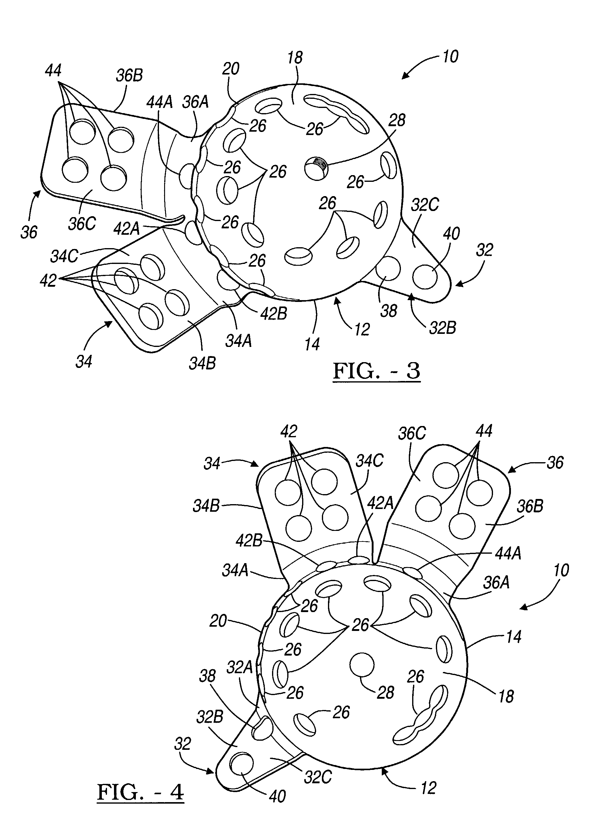
[0042]The following description of the embodiments concerning a method and apparatus for providing a modular acetabular prosthesis for use in orthopedic surgical procedures, and trials therefore, are merely exemplary in nature and are not intended to limit the invention or its application or uses. Moreover, while the present invention is described in detail below with reference to performing a revision type implantation procedure, it will be appreciated by those skilled in the art, that the present invention is clearly not limited to only revision type orthopedic surgical procedures and may be used with various other orthopedic surgical procedures as well.

[0043]Referring to FIGS. 1-5, an acetabular prosthesis 10, according to a general embodiment, is shown. The acetabular prosthesis 10 includes a modified hemispherical acetabular cup 12. The acetabular cup 12 is said to be “hemispherical” in that it is not a perfect hemisphere; but rather, it includes an arcuate portion 14 extending...


PUM


Abstract

A trial system for an acetabular prosthesis is described. The acetabular prosthesis is generally for implantation in an acetabulum and surrounding pelvis. The acetabular prosthesis includes an acetabular cup having a substantially concave inner surface and a substantially convex outer surface. The described acetabular prosthesis is especially useful in revision hip implant procedures where significant bone tissue loss has occurred either in or around the acetabulum and / or the pelvis. A trial shell is provided to trial a range of motion of the hip joint before implanting a prosthetic shell into the acetabular prosthesis.

Description

CROSS-REFERENCE TO RELATED APPLICATIONS[0001]This application is a continuation-in-part of U.S. patent application Ser. No. 09 / 792,174 filed on Feb. 23, 2001, now U.S. Pat. No. 6,458,161 entitled, “A METHOD AND APPARATUS FOR ACETABULAR RECONSTRUCTION,” currently pending.TECHNICAL FIELD[0002]This invention relates generally to a method and apparatus for use in orthopedic surgery and, more particularly, to a method and apparatus for trialing a modular acetabular prosthesis having various modular attachment components for use during an orthopedic surgical procedure.BACKGROUND[0003]A natural hip joint may undergo degenerative changes due to a variety of etiologies. When these degenerative changes become so far advanced and irreversible, it may ultimately become necessary to replace a natural hip joint with a prosthetic hip. When implantation of such a hip joint prosthesis becomes necessary, the head of the femur, the acetabular, or both may need to be replaced. The head of the natural f...

Claims


Application Information

Patent Timeline
Patent Type & Authority Patents(United States)
IPC IPC(8): A61F2/32A61B17/86A61F2/00A61F2/02A61F2/28A61F2/30A61F2/34A61F2/46
CPCA61F2/30724A61F2/30734A61F2/4684A61F2/34A61F2250/0058A61F2002/30535
Inventor GIBBS, PHILLIP M
Owner BIOMET MFG CORP
Why Eureka
Try Eureka