Vertebral shock absorbers

a technology of shock absorption and vertebrae, which is applied in the field of spine surgery, can solve the problems of pain in the back or legs, nerve injury, and risk of future nerve injury, and achieve the effect of facilitating lateral application and enhancing range of motion

Inactive Publication Date: 2005-11-24
FERREE BRET A
View PDF11 Cites 191 Cited by
  • Summary
  • Abstract
  • Description
  • Claims
  • Application Information

AI Technical Summary

Benefits of technology

[0009] This invention improves upon existing devices by providing a vertebral shock absorber in the form of an elongated compressible member having two ends, one fastened to an upper vertebra, and the other fastened to a lower vertebra. The elongated member may be fastened using pedicle screws or by way of ball-and-socket joints for enhanced range of motion.
[0010] In the preferred embodiment the elongated comp

Problems solved by technology

Such problems may include pain in the back or legs, nerve injury, risk of future nerve injury, or spinal deformity.
Although such devices provide some level of shock absorption,

Method used


Image

  • Vertebral shock absorbers
  • Vertebral shock absorbers
  • Vertebral shock absorbers

Examples


Embodiment Construction

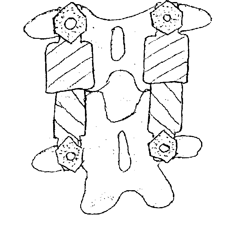
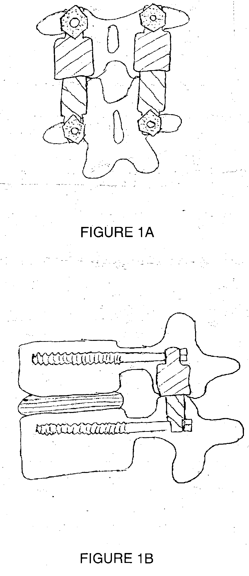
[0020] Broadly, this invention covers the use of “shock absorbers” on the posterior, lateral, or anterior aspect of the spine. FIG. 1A is a view of the posterior aspect of the posterior embodiment of the invention and the spine. FIG. 1B is sagittal cross section of the spine and the embodiment of the device drawn in FIG. 1A. In the posterior embodiment, the vertebral shock absorbers are connected to pedicle screws. Note that the devices could be used as an adjunct to arthroplasty devices placed in the disc space.

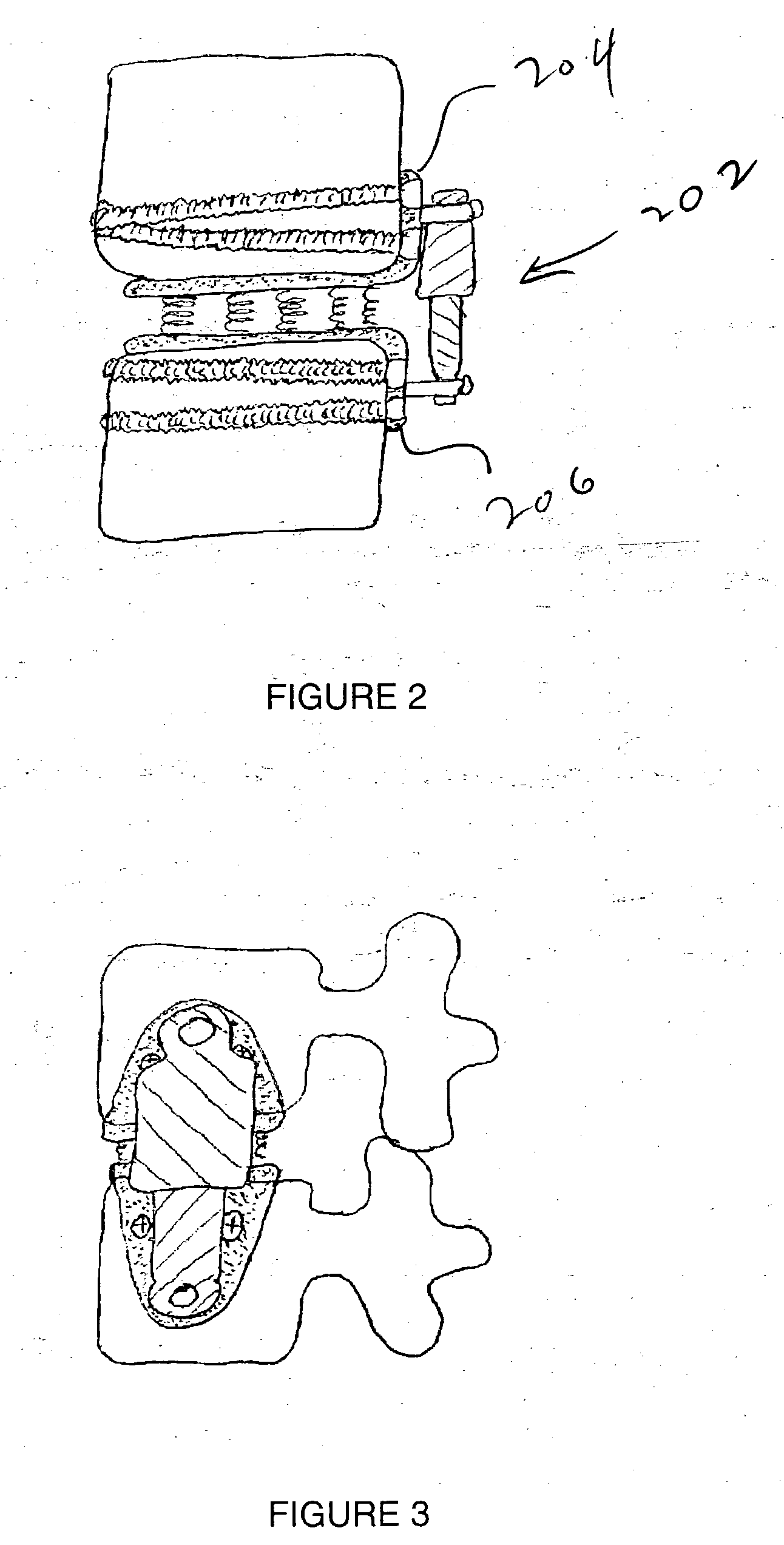
[0021]FIG. 2 is a coronal cross section of the spine and an embodiment of the invention particularly suited to the anterior or lateral aspect of the spine. FIG. 3 is a view of the lateral side of the spine and the embodiment of the invention drawn in FIG. 2. In this case a vertebral shock absorber 202 is connected to plates 204, 206 that are attached to the lateral aspect of the spine. The plates are preferably connected to the spine by diverging or converging screws. The s...


PUM


Abstract

A vertebral shock absorber in the form of an elongated compressible member having two ends, one fastened to an upper vertebra, and the other fastened to a lower vertebra. The elongated member may be fastened using pedicle screws or by way of ball-and-socket joints for enhanced range of motion. In the preferred embodiment, the elongated compressible member is constructed using telescoping sleeves to create a cavity wherein there is disposed a compressible, resilient component such as a spring, elastomeric material, liquid, gel, hydrogel, or other suitable substance. The shock absorber may be combined with an intradiscal component and/or one or more plates that extends at least partially onto a vertebral endplate to facilitate lateral application.

Description

REFERENCE TO RELATED APPLICATION [0001] This application claims priority from U.S. Provisional Patent Application Ser. No. 60 / 372,754, filed Apr. 13, 2002, the entire content of which is incorporated herein by reference.FIELD OF THE INVENTION [0002] This invention relates generally to spinal surgery and, in particular, to shock-absorbing structures spanning vertebral levels. BACKGROUND OF THE INVENTION [0003] The problems created by disc degeneration, facet arthritis, and other conditions such as spondylolysis, spondylolisthesis, scoliosis, fracture, tumor, or infection are frequently treated by spinal fusion. Such problems may include pain in the back or legs, nerve injury, risk of future nerve injury, or spinal deformity. [0004] The goal of spinal fusion is to successfully “grow” two or more vertebrae together. To achieve this, bone from the patient's body (spine or iliac crest) or from cadavers, is often grafted between vertebrae. Alternatively, bone graft substitutes, such as hy...

Claims


Application Information

Patent Timeline
IPC IPC(8): A61B17/70A61F2/44
CPCA61B17/7007A61B17/7025A61F2/442A61B17/7044A61B17/7031
Inventor FERREE, BRET A.
Owner FERREE BRET A
Why Eureka
Try Eureka