Use of autonomous moveable obstructions as seismic sources

a technology of moving obstructions and seismic sources, applied in the field of hydrocarbon production, can solve the problems of long data processing cycles of subsurface vsp and 3d vsp, inability to use near real-time, and inability to acquire repeat 3d seismic data,

Inactive Publication Date: 2003-12-16
BAKER HUGHES INC
View PDF10 Cites 27 Cited by
  • Summary
  • Abstract
  • Description
  • Claims
  • Application Information

AI Technical Summary

Problems solved by technology

The conventional 3D and 4D surveys provide data with limited spatial resolution and no near real-time ability to utilize results because of the lengthy time span required to acquire and process the data, which can take several months.
The subsurface VSP and 3D VSP also suffer from long data processing cycles and have limited spatial extent.
Another related problem is the expense of acquiring repeat 3D seismic data over a relatively small geographical area, such as between 10-20 Km.sup.2.
Ocean bottom cable surveys, wherein seismic sensor or detector cables are deployed on the sea bottom, provide an alternative surveying method but are more expensive than the towed streamer cable acquisition methods.
This criterion is severe because changes in the data-acquisition equipment and changes in the processing algorithms, inevitable over many years may introduce differences among the separate, individual data sets from surveys that are due to instrumentation, not the result of dynamic reservoir changes.
In particular, using conventional surface exploration techniques, long-term environmental changes in field conditions such as weather and culture may affect the outcome.
The requirement for an active source to be placed at various levels in the bore hole is problematic because the source can damage the hole and interfere with production.
Since the seismic equipment must be moved up and down the bore hole, it is difficult, using conventional methods, to precisely locate and / or position seismic equipment to maintain identical recording conditions over an extended time period.
The Winbow system, thus is difficult to implement for the fixed permanent instrumental installation required for 4-D seismic monitoring operation.

Method used


Image

  • Use of autonomous moveable obstructions as seismic sources
  • Use of autonomous moveable obstructions as seismic sources
  • Use of autonomous moveable obstructions as seismic sources

Examples


Embodiment Construction

The present invention functions in at least two distinct but related modes for using autonomous carriers to convert acoustic tube waves into body waves or provide sesimic sources deployed by autonomous carriers. The first mode provides a near, real-time method to acquire seismic data in and / or above a reservoir at very high spatial resolution such that advancing fluid fronts and hydrocarbons can be detected. The second mode provides an alternative method of acquiring repeat 3-D seismic surveys over small areas. Both methods enable investigation of large spatial extents at arbitrarily fine spatial intervals.

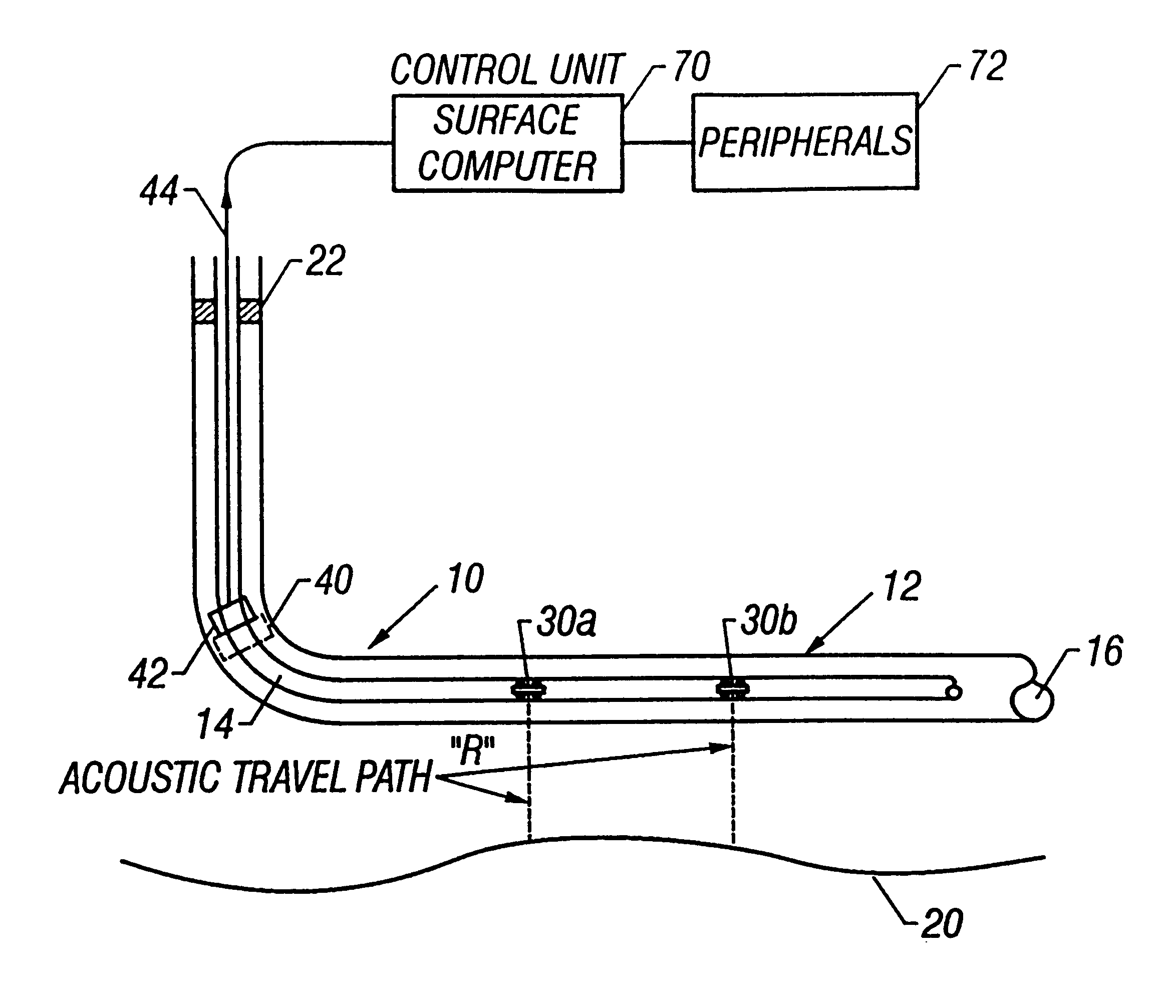
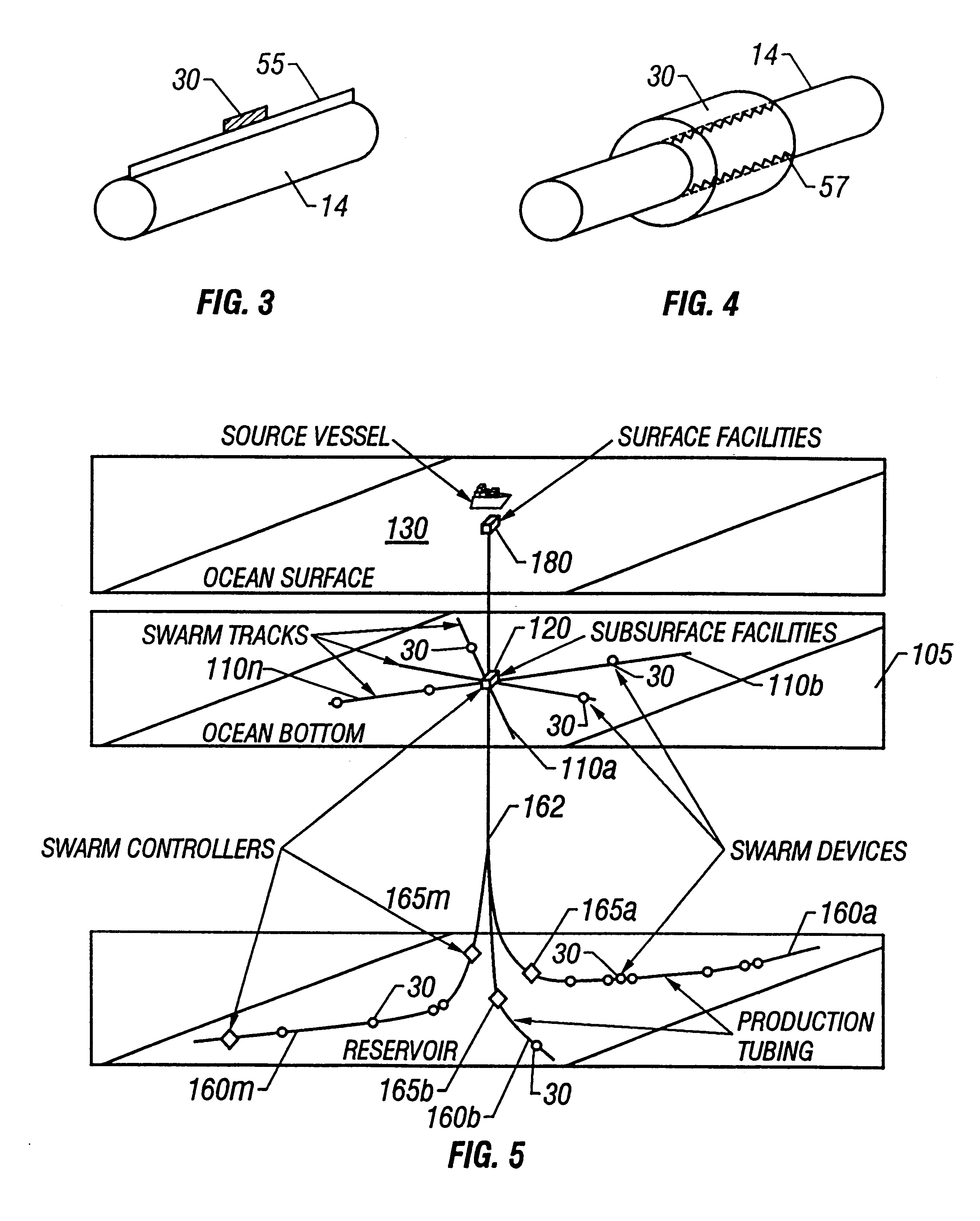
The system and methods of the present invention may be utilized for subsurface (i.e. in-hole), earth surface applications and ocean bottom applications. FIGS. 1 and 2 illustrate examples of in-hole applications. FIG. 1 is a schematic diagram of a production well 10 that is producing hydrocarbons from a reservoir R.sub.1. The well 10 is shown to include a horizontal section 12 form...


PUM


Abstract

One or more autonomous devices are deployed in the well to provide a moveable sensor source or obstruction for coupling a tube wave seismic signal into the formation adjacent the well bore. The autonomous devices move in the well and provide moveable obstructions or discontinuities which couple tube waves existing in the well bore or production tubing into the formation adjacent the well bore. Wellbore tube wave energy is converted to body wave energy at minor borehole obstructions or irregularities that become sources of seismic energy. A well bore may contain a plurality of minor obstructions or discontinuities. Each obstruction or discontinuity position along the borehole has an associated unique waveform source coda that may be measured for processing the wavefield radiated into the earth formation surrounding the well bore. A plurality of sensors detects the radiated seismic energy after the seismic energy has transited intervening earth formations. The system may be employed as a permanent monitoring device for mineral resource management so that measurements may be acquired at many different times. A time lapse profile may be created that is representative of the temporal and areal changes in the petrophysical characteristics and mineral content or distribution of the intervening earth formation.

Description

1. Field of the InventionThis invention relates generally to the production of hydrocarbons from subsurface formations and to in-hole seismic data acquisition to map advancing fluid fronts and the depletion of hydrocarbons within a hydrocarbon producing formation around a single well bore or outside a well bore on the surface of the earth or on the ocean bottom. The invention relates specifically to an autonomous carrier providing a movable obstruction, the carrier providing a seismic source or a discontinuity or obstruction to convert tube waves to body waves, the carrier being movable inside and outside the well bore and on the earth's surface or on the ocean bottom.2. Description of the Related ArtIn order to relatively precisely map advancing fluid fronts within a field or around a single well bore requires the use of deep reading measurements at spatial resolutions of less than five (5) meters but with the spatial extents of several hundred meters, depending upon the reservoir ...

Claims


Application Information

Patent Timeline
Patent Type & Authority Patents(United States)
IPC IPC(8): G01V1/42G01V1/40
CPCG01V1/42G01V1/40
Inventor NORRIS, MICHAELARONSTAM, PETER
Owner BAKER HUGHES INC
Why Eureka
Try Eureka