
Method and system using power modulation and velocity modulation producing sputtered thin films with sub-angstrom thickness uniformity or custom thickness gradients

a technology of power modulation and velocity modulation, applied in the direction of vacuum evaporation coating, optical elements, instruments, etc., can solve the problems of radial non-uniform coating thickness, tedious and inefficient process, lack of flexibility of masks or baffles,

Inactive Publication Date: 2003-12-23
EUV
View PDF9 Cites 27 Cited by
  • Summary
  • Abstract
  • Description
  • Claims
  • Application Information

AI Technical Summary

Problems solved by technology

However, radial non-uniformities in coating thickness typically result.
The masking operation requires iteration of the shape of the mask, and can be impractical for cases where perfect thickness distribution control is required at the location that coincides with the axis of rotation.
At best, this is a tedious and inefficient process that is inappropriate for a robust manufacturing technique.
The use of masks or baffles also lacks flexibility when several substrates must be coated in the same deposition run using several deposition sources.
If differently customized masks are attached in close proximity to the substrates to intercept part of the incident deposition flux, custom coating gradients can be obtained for each substrate but one cannot independently control the flux emitted by each source.
On the other hand, if differently customized masks are installed over the sources to shape the outgoing deposition flux, customized coating gradients can be obtained from each source but one cannot independently control the coating gradients deposited on several different substrates.
This would require another mask fabrication and perhaps venting the chamber to atmosphere (undesirable) to install the new mask.
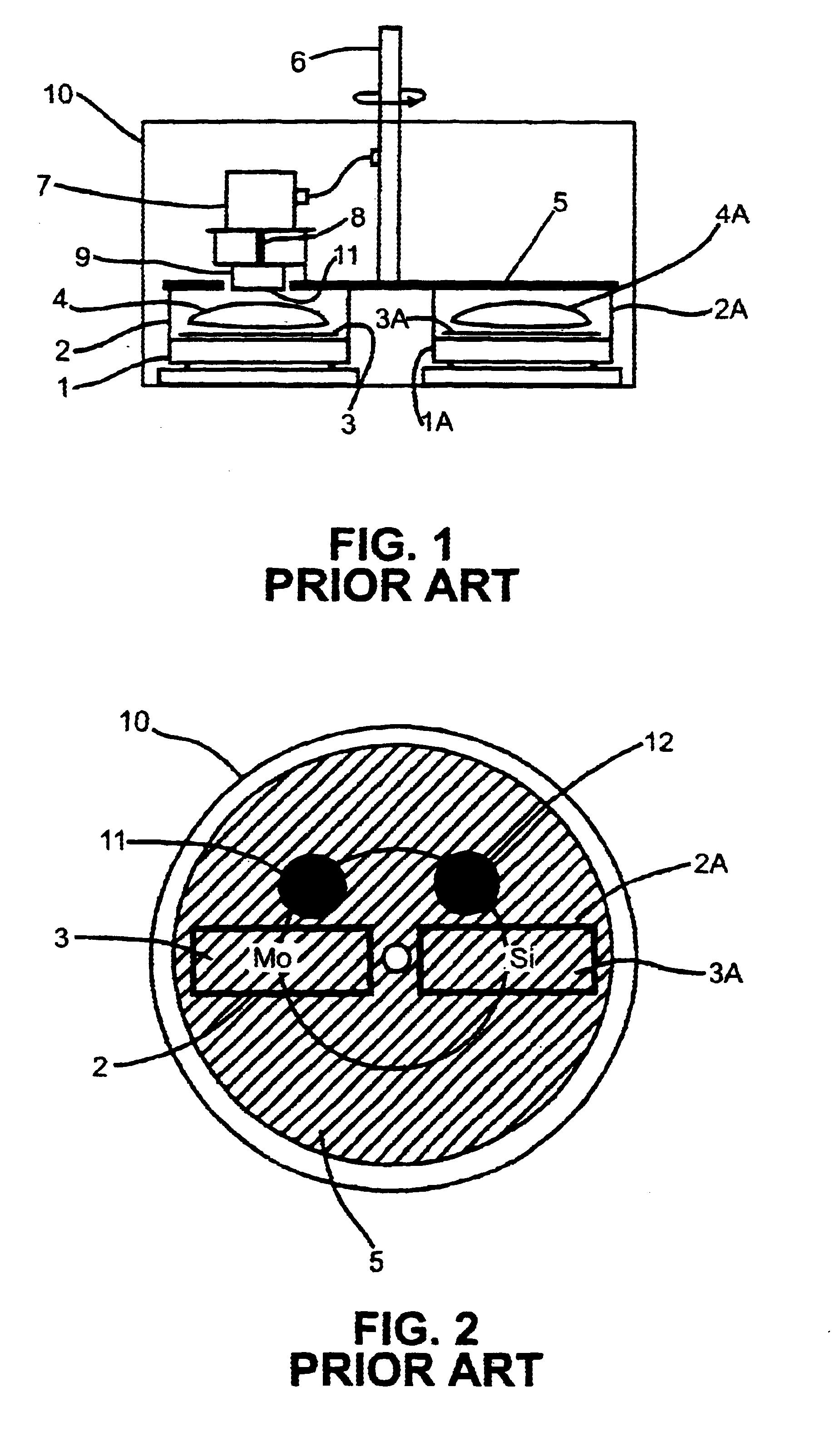
The inventors of the present invention, however, have recognized that it can be difficult to engineer and control such systems in which a load of multiple, heavy substrates (or vapor deposition sources) must be precisely accelerated and decelerated to various velocities within very short distances.
The requirements for acceleration / deceleration of heavy substrates can significantly complicate the design of the substrates' drive mechanism and increase the cost of the vapor deposition tool.
The inventors have recognized that slow spin speeds for the substrate (while the substrate is swept across the source) give rise to a ripple effect (rapid oscillation of coating thickness as a function of radius cross the substrate), which may or may not be acceptable for specific applications.

Method used


Image

  • Method and system using power modulation and velocity modulation producing sputtered thin films with sub-angstrom thickness uniformity or custom thickness gradients
  • Method and system using power modulation and velocity modulation producing sputtered thin films with sub-angstrom thickness uniformity or custom thickness gradients
  • Method and system using power modulation and velocity modulation producing sputtered thin films with sub-angstrom thickness uniformity or custom thickness gradients

Examples


Embodiment Construction

The invention pertains to methods and systems for vapor deposition (such as sputtering, CVD, and electron beam evaporation methods and systems) in which a substrate to be coated is passed through a vapor of the coating material and accumulates a film (typically a very thin film) of the coating material through condensation of the vapor.

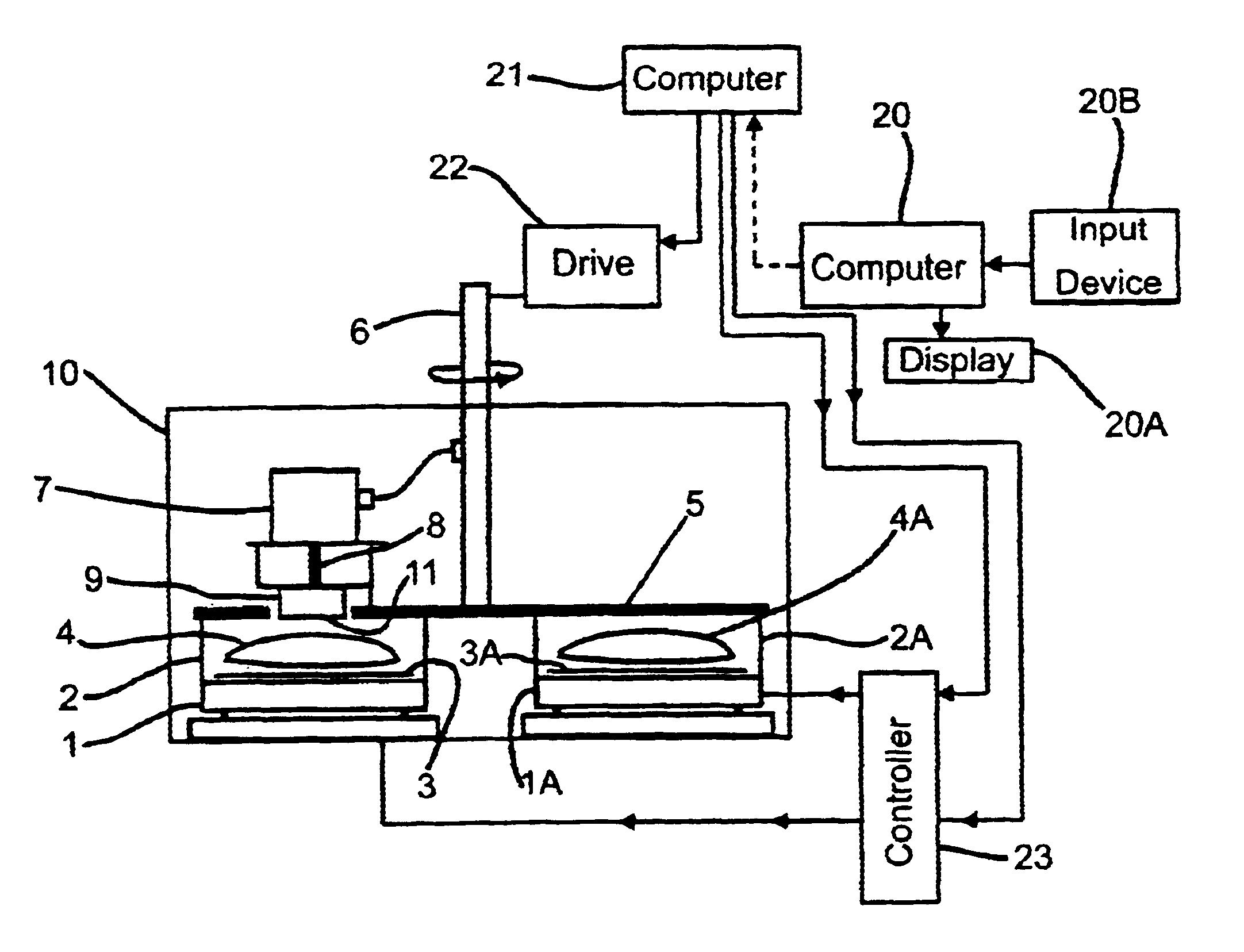
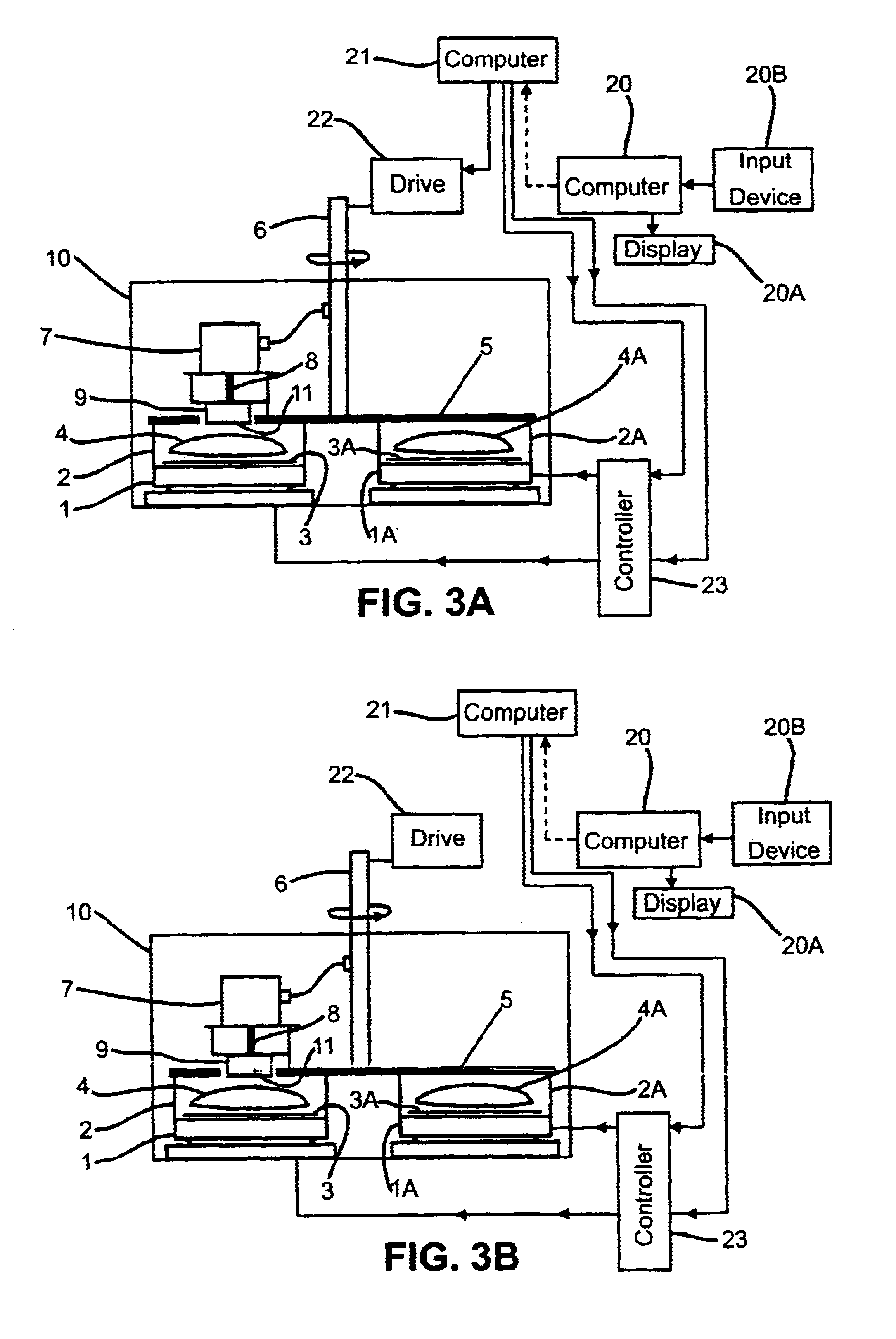
The invention provides a method producing uniform or graded thin film and multilayer coatings on substrates with any surface curvature in a manner avoiding use of apertures or masks to tailor the deposition flux profile. In accordance with the invention, the power applied to a vapor deposition source is modulated (or the flux distribution of the source is otherwise modulated) as one or more substrates sweep across the source with controlled velocity (preferably a constant velocity, but optionally a time-varying velocity) to generate a thicker or thinner coating in some substrate regions relative to other substrate regions. Typically, the substrate als...


PUM

PropertyMeasurementUnit
pressureaaaaaaaaaa
azimuthal uniformityaaaaaaaaaa
heightaaaaaaaaaa

Abstract

A method and system for determining a source flux modulation recipe for achieving a selected thickness profile of a film to be deposited (e.g., with highly uniform or highly accurate custom graded thickness) over a flat or curved substrate (such as concave or convex optics) by exposing the substrate to a vapor deposition source operated with time-varying flux distribution as a function of time. Preferably, the source is operated with time-varying power applied thereto during each sweep of the substrate to achieve the time-varying flux distribution as a function of time. Preferably, the method includes the steps of measuring the source flux distribution (using a test piece held stationary while exposed to the source with the source operated at each of a number of different applied power levels), calculating a set of predicted film thickness profiles, each film thickness profile assuming the measured flux distribution and a different one of a set of source flux modulation recipes, and determining from the predicted film thickness profiles a source flux modulation recipe which is adequate to achieve a predetermined thickness profile. Aspects of the invention include a computer-implemented method employing a graphical user interface to facilitate convenient selection of an optimal or nearly optimal source flux modulation recipe to achieve a desired thickness profile on a substrate. The method enables precise modulation of the deposition flux to which a substrate is exposed to provide a desired coating thickness distribution.

Description

1. Field of the InventionThe invention relates to methods and apparatus for producing thin films on substrates by vapor deposition (e.g., sputtering). The invention pertains to improving the accuracy of the deposited film thickness across the substrate (e.g., by improving the uniformity of the film thickness across the substrate where it is desired to deposit a film having uniform thickness). The invention presents the particular advantage of avoiding the use of apertures or masks to tailor the deposition profile.2. Discussion of the Related ArtThin film coatings are typically produced by various vapor deposition methods (such as sputtering, chemical vapor deposition (CVD), electron beam evaporation, thermal evaporation, and ion beam plating) in which the substrate to be coated is passed through a vapor of the coating material and accumulates a thin film through condensation of the vapor. For many applications, such as optical films for EUV (extreme ultraviolet) lithography, it is d...

Claims


Application Information

Patent Timeline
Patent Type & Authority Patents(United States)
IPC IPC(8): C23C14/54G02B1/10
CPCC23C14/54G02B1/10C23C14/545C23C14/543
Inventor MONTCALM, CLAUDEFOLTA, JAMES ALLENWALTON, CHRISTOPHER CHARLES
Owner EUV
Learn More