Optical fiber organizer for organizing optical fiber inside of a fiber duct

a technology of optical fiber and organizer, which is applied in the direction of optics, fibre mechanical structures, instruments, etc., can solve the problems of increasing the density of optical transceivers, and increasing the complexity of optical network components

Inactive Publication Date: 2003-12-30
CIENA
View PDF7 Cites 15 Cited by
  • Summary
  • Abstract
  • Description
  • Claims
  • Application Information

AI Technical Summary

Problems solved by technology

Modem computer and telecommunications networks are constantly growing more complex and have an ever-expanding need for bandwidth (the ability to accept, process, and / or transmit information).
One of the ways that optical network components have become more complex over the years is through an increased density of optical transceivers and fibers.
This solution is limited, because it only serves to retain optical fibers within the duct 3.
The use of a single space to retain all the fibers of a telecommunications device is less than desirable for several reasons.
First, it is difficult to determine which fiber is which when it comes time to service the device if all 512 fibers are contained in the duct with no grouping or other organization.
As a result, it can be cumbersome to access the fibers that happen to be at the rear of the fiber duct owing to the potentially large number of fibers in front of them.
Further, if one wishes to remove a fiber towards the rear of the duct, one must also remove a number of fibers in front of it, thereby making the process cumbersome and slow.

Method used


Image

  • Optical fiber organizer for organizing optical fiber inside of a fiber duct
  • Optical fiber organizer for organizing optical fiber inside of a fiber duct
  • Optical fiber organizer for organizing optical fiber inside of a fiber duct

Examples


third embodiment

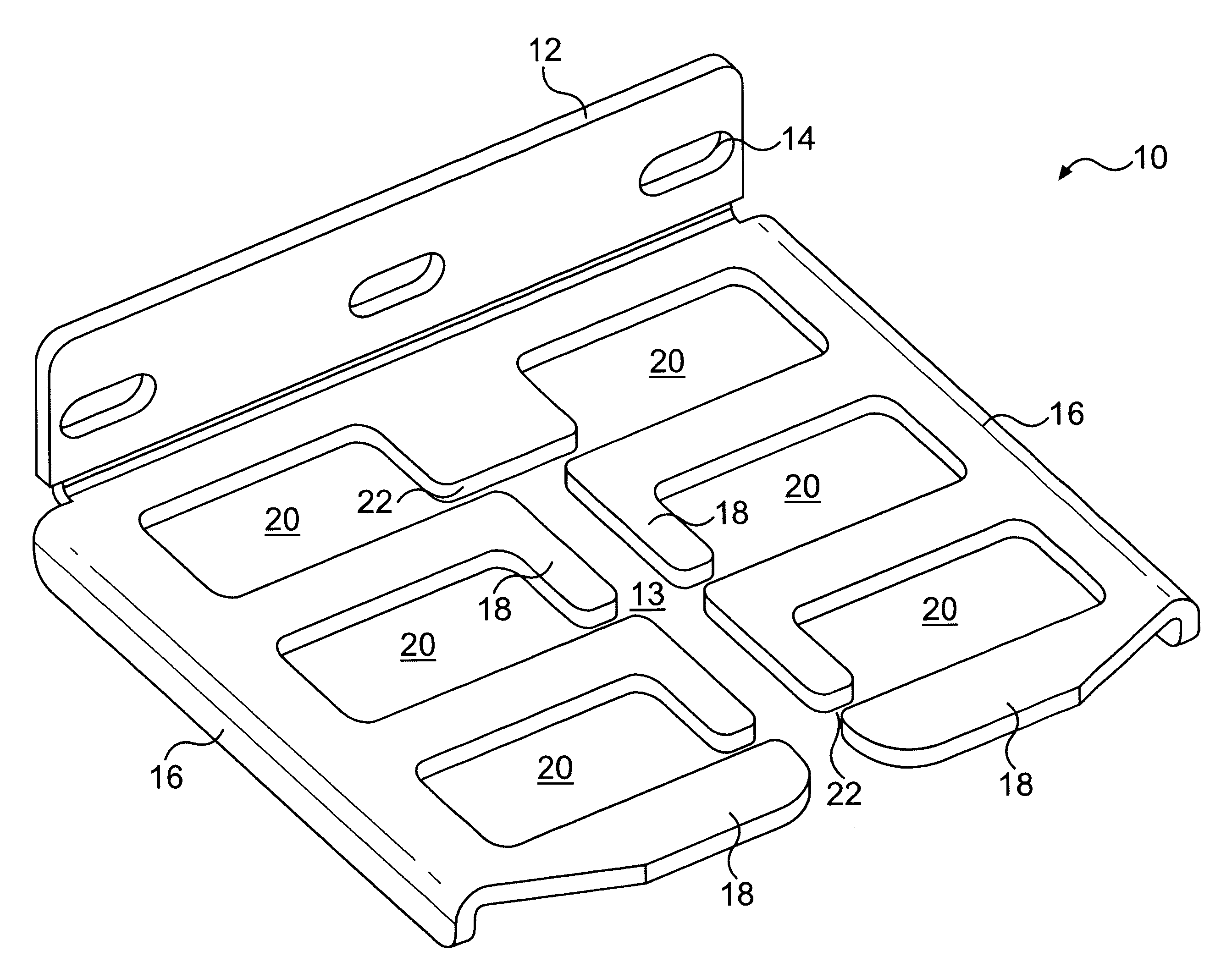
FIG. 4 depicts the invention in the form of fiber organizer 110. It, too, includes a bracket 112 with at least one side arm 116. In the prior embodiments, the retaining arms 18 are substantially flat. Here, arms 118 divide the central space into vertical sub-spaces 120, because arms 118 are substantially perpendicular to the plane of organizer 110. That is, each arm 118 is relatively planar, and the basic plane of each arm is roughly 90.degree. from the overall plane of bracket 112. As with the prior embodiments, gaps 122 are provided between adjacent arms 118 to allow for the intentional entry and removal of optical fibers within sub-spaces 120. In the specific organizer shown in FIG. 4, the gap is made more effective at preventing unintentional egress of fibers by providing a tab 124 and a corresponding cutout 126 on retaining arms 118. Each arm 118 is provided on one side with a tab 124 and on the other side with a cutout 126. The tab of one arm 118 corresponds to the cutout of a...

fifth embodiment

A fifth embodiment is shown in FIGS. 6A-E. Rather than fabricating a multi-pronged, multi-bend piece of metal or plastic such as those shown in FIGS. 2-5, the fiber organizer 310 of FIG. 6 is much simpler to manufacture, because it utilizes an existing off-the-shelf component. Like the above embodiments, fiber organizer 310 includes a mounting bracket 312 having mounting holes 314 and side arms 316. However, instead of being provided with integral retaining arms as above, the invention is meant to work with existing attachable fiber guides 318. These fiber guides 318 are currently manufactured by Richco, Inc. and are currently used to hang cables or fibers along the interiors of devices. They have not been used in fiber ducts, and they have not been used in groups such as disclosed here.

As shown in FIG. 6C, fiber guide 318 is provided with a retaining ring 323 which surrounds and defines a retaining space 320. Ring 323 is provided with a gap 322 to allow entry and egress of fibers t...


PUM


Abstract

An optical fiber organizing device is provided. The inventive fiber organizer includes a bracket preferably fittable inside an optical fiber duct of a telecommunications device and a plurality of retaining arms extending from the bracket dividing the main internal space into a plurality of internal sub-spaces. Each of the sub-spaces is adapted to retain bundles of optic fibers. The optical fiber organizer may be made from a single piece, for example, a single piece of stamped sheet metal. Alternatively, the retaining arms may be separate pieces made from resilient plastic. In either event, the retaining arms are preferably resilient and bendable to allow for intentional insertion and extraction of optical fibers while not allowing for the unintentional egress of fibers.

Description

1. Field of the InventionThe invention relates to devices which employ optical fiber; more specifically, the invention relates to a device that manages and organizes optical fibers for use in an optical telecommunications device.2. Description of Related ArtModem computer and telecommunications networks are constantly growing more complex and have an ever-expanding need for bandwidth (the ability to accept, process, and / or transmit information). Many of the components used in such networks utilize optical transceivers and optical fibers as the means of communicating among and within the various components.One of the ways that optical network components have become more complex over the years is through an increased density of optical transceivers and fibers. Typically, the optical fibers employed in a telecommunications device are mounted at one end to a transceiver on a circuit board of some sort; the other end of the fiber exits the device to be connected to other devices or other...

Claims


Application Information

Patent Timeline
Patent Type & Authority Patents(United States)
IPC IPC(8): G02B6/44
CPCG02B6/4471G02B6/4459
Inventor GEHRKE, GARY CURTIS
Owner CIENA
Why Eureka
Try Eureka