Friction stir welding of corner configurations

Inactive Publication Date: 2004-01-13
EDISON WELDING INSTITUTE INC
View PDF29 Cites 87 Cited by
  • Summary
  • Abstract
  • Description
  • Claims
  • Application Information

AI Technical Summary

Benefits of technology

will become apparent from the following disclosure in which one or more preferred embodiments of the invention are described in detail and illustrated in the accompanying drawings. It is contemplated that variations in size, structural features and probe designs may appear, to a person skilled in the art, without departing from the scope of or sacrificing any of the advantages of the invention.

Problems solved by technology

Welding with this type of joint configuration with the backing plates firmly against the horizontal and vertical members and a standard friction stir welding tool (tapered or straight probe) often produces a crevice at the point where the horizontal and vertical work pieces contact each other because the probe has not properly mixed the plasticized materials.

Method used


Image

  • Friction stir welding of corner configurations
  • Friction stir welding of corner configurations
  • Friction stir welding of corner configurations

Examples


Embodiment Construction

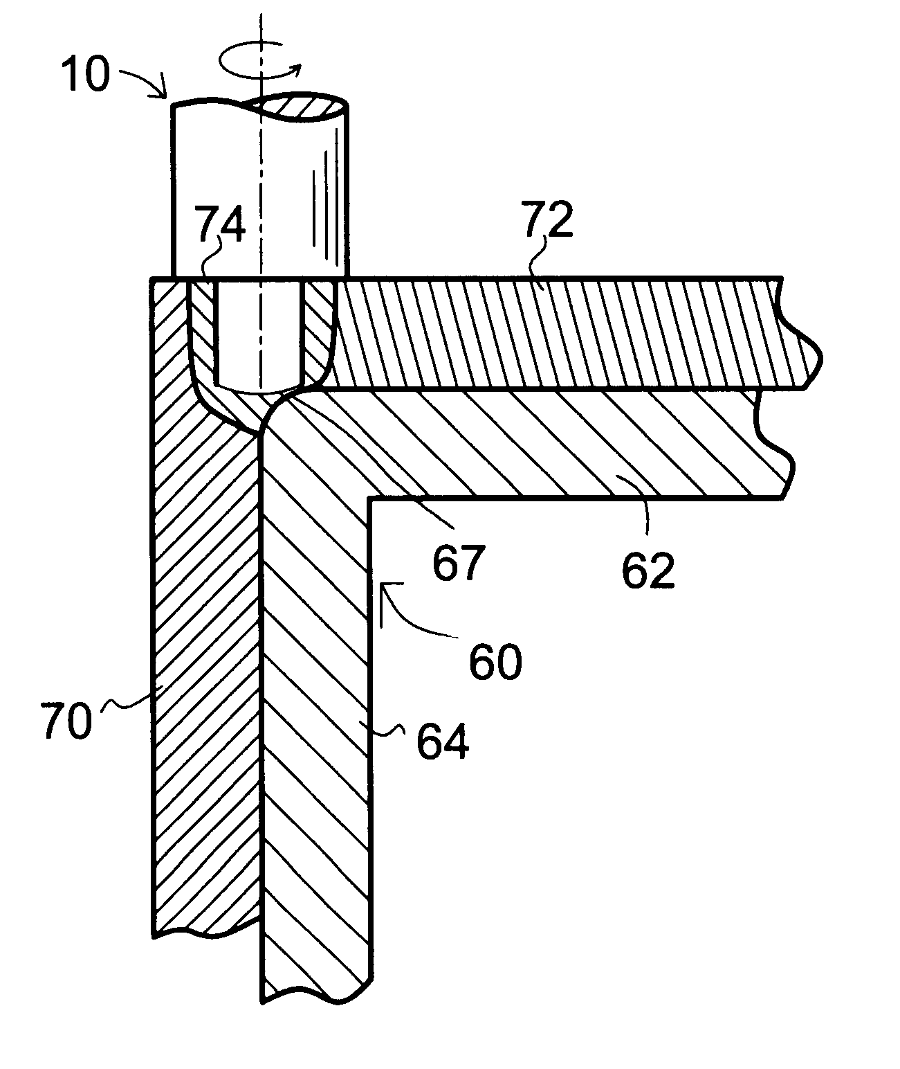
As used in this application, the following words have the following meanings. "Corner" refers to a configuration in which a first horizontal member meets a second angled member. Although typically the second angled member meets the horizontal member at a right (90 degree) angle, a wide range of other angles are also contemplated by the term corner. The term "horizontal" is used only for orientational purposes and is in no way limiting, it being realized that any orientation may be selected for the first member and a second member angled to meet the first member in a corner configuration. "Proximity" refers to parts that are either in contract with each other or with a minimum gap between the parts, it being realized the some surface variation in work piece units are possible and that contact is not always possible along the intended contacting region of the work pieces or slight separation may occur during the setup process. However, gaps, especially large gaps are to be avoided as ...


PUM

PropertyMeasurementUnit
thicknessaaaaaaaaaa
curvatureaaaaaaaaaa
anglesaaaaaaaaaa

Abstract

A radiused corner support plate is used to form a corner void when making L- and T-corner welds that are filled with plasticized work piece material during friction stir welding to form a filleted corner weld. An improved friction stir welding tool uses either disrupting features such as crossed rectangular grooves in the distal tip end or a curved tip region or both to improve plasticized work piece material flow below the distal end and in the region of the fillet.

Description

1. Field of the InventionThis invention pertains to friction stir welding and more particularly to a backing plate and a friction stir welding probe for making L- and T-type filleted corner joints.2. Background of the InventionFriction stir welding is a relatively new welding technique discovered in the mid-1990s that was developed primarily for welding aluminum and soft aluminum alloys that were difficult to weld using traditional welding techniques. The technique uses a rotating shouldered cylindrical tool with a projecting probe (also referred to as a pin) to generate heat in the workpiece. The mechanical friction of the rotating tool contacts the workpiece and plasticizes (softens) the metal as it is plunged into the bondline. At this stage, there is a substantial amount of plasticized metal in a column about the rotating pin beneath the shoulder of the cylinder portion of the tool. The tool is then moved along the bondline relative to the workpiece. As the pin rotates and moves...

Claims


Application Information

Patent Timeline
Patent Type & Authority Patents(United States)
IPC IPC(8): B23K20/12
CPCB23K20/1255B23K20/126B23K20/1265
Inventor TRAPP, TIMOTHY J.STOTLER, TIMOTHYSKILLITER, MATHEW
Owner EDISON WELDING INSTITUTE INC
Why Eureka
Try Eureka