
Leg stretching device

a leg stretching and leg technology, applied in the field of leg stretching devices, can solve the problems of unfavorable use, unfavorable use, unduly complicated and expensive, and achieve the effect of improving or increasing the flexibility of the user in his/her ability

Inactive Publication Date: 2004-05-11
BUSSELL ERNIE L
View PDF11 Cites 36 Cited by
  • Summary
  • Abstract
  • Description
  • Claims
  • Application Information

AI Technical Summary

Benefits of technology

"The invention is a leg stretching device that is simple and safe for users. It applies pressure to the thighs of the user to improve flexibility in performing side splits. The device includes a seat, a rail, and a reciprocating sleeve with linking arms and leg deck. The actuating means is a hydraulic cylinder that is actuated by the user. The device is designed to be opened and closed by the user and has a flexible length to accommodate users of different height or size. The technical effect of this invention is to provide a simple and effective tool for improving flexibility and performance in sports and other activities."

Problems solved by technology

However, most of these devices apply pressure mainly on the ankles.
The exercising machines disclosed and known in the prior art require a pulling action in contrast to a pushing action, or apply pressure at the ankles, or appear to be unduly complicated and expensive.

Method used


Image

  • Leg stretching device
  • Leg stretching device
  • Leg stretching device

Examples


Embodiment Construction

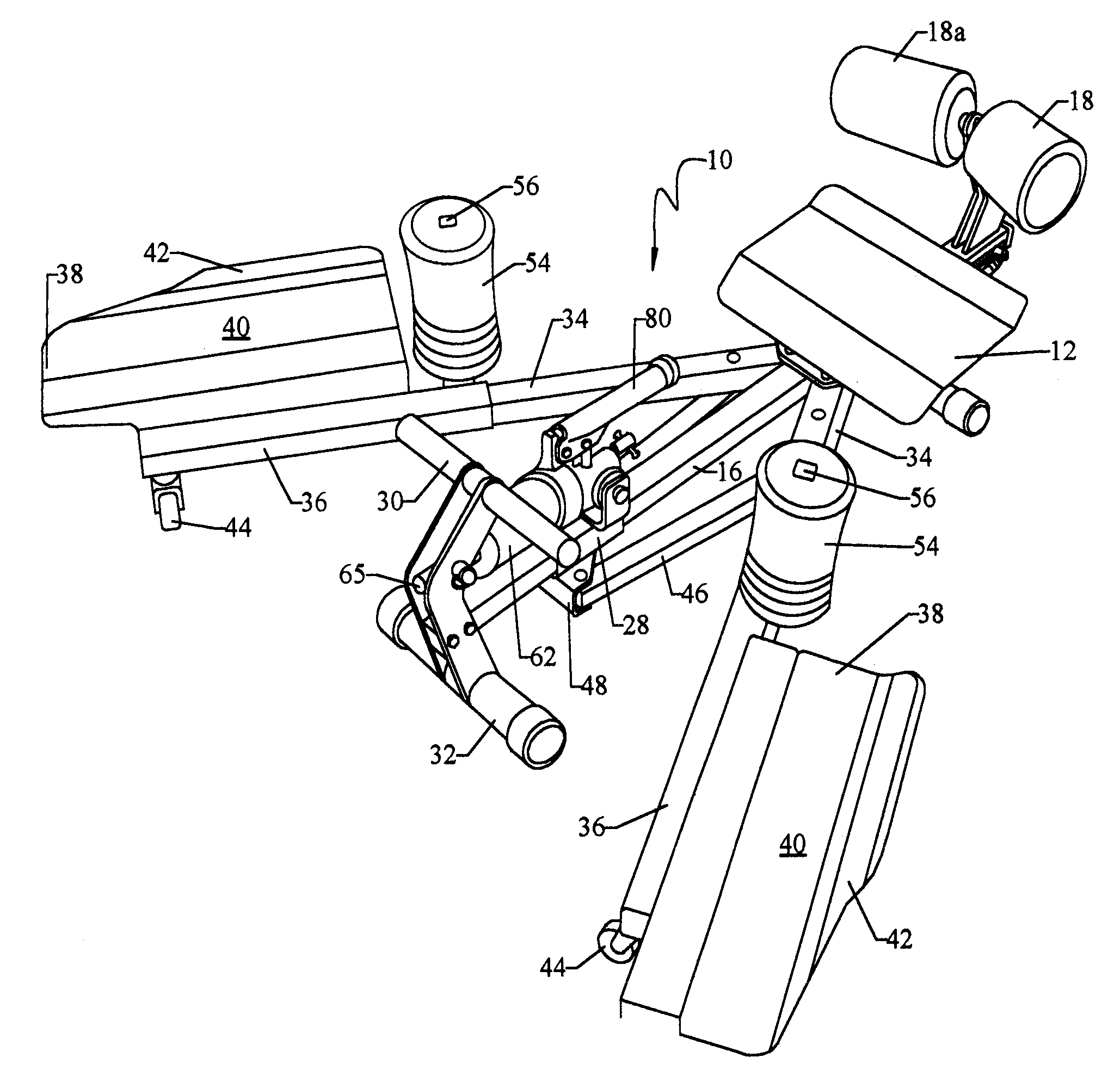
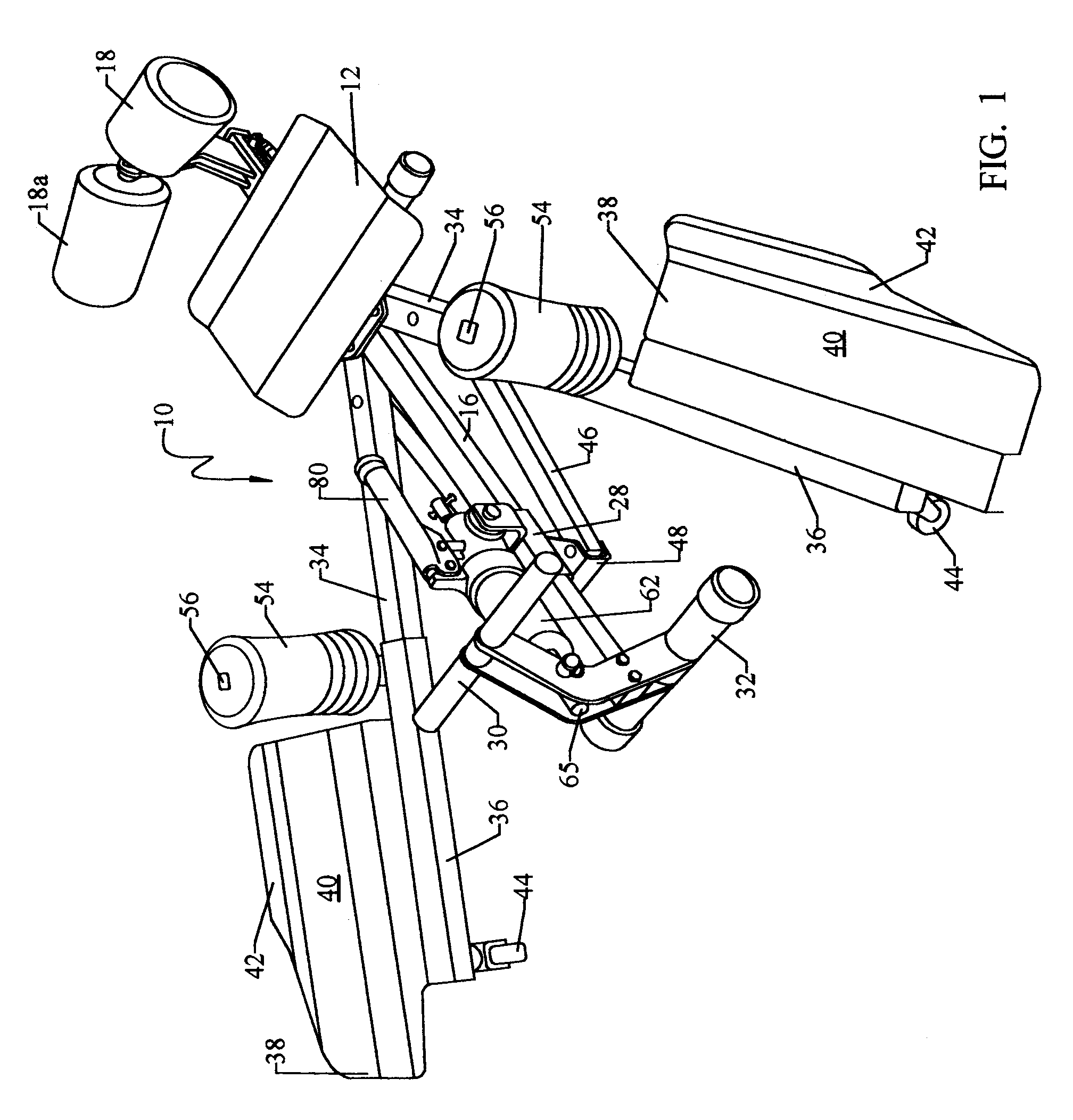
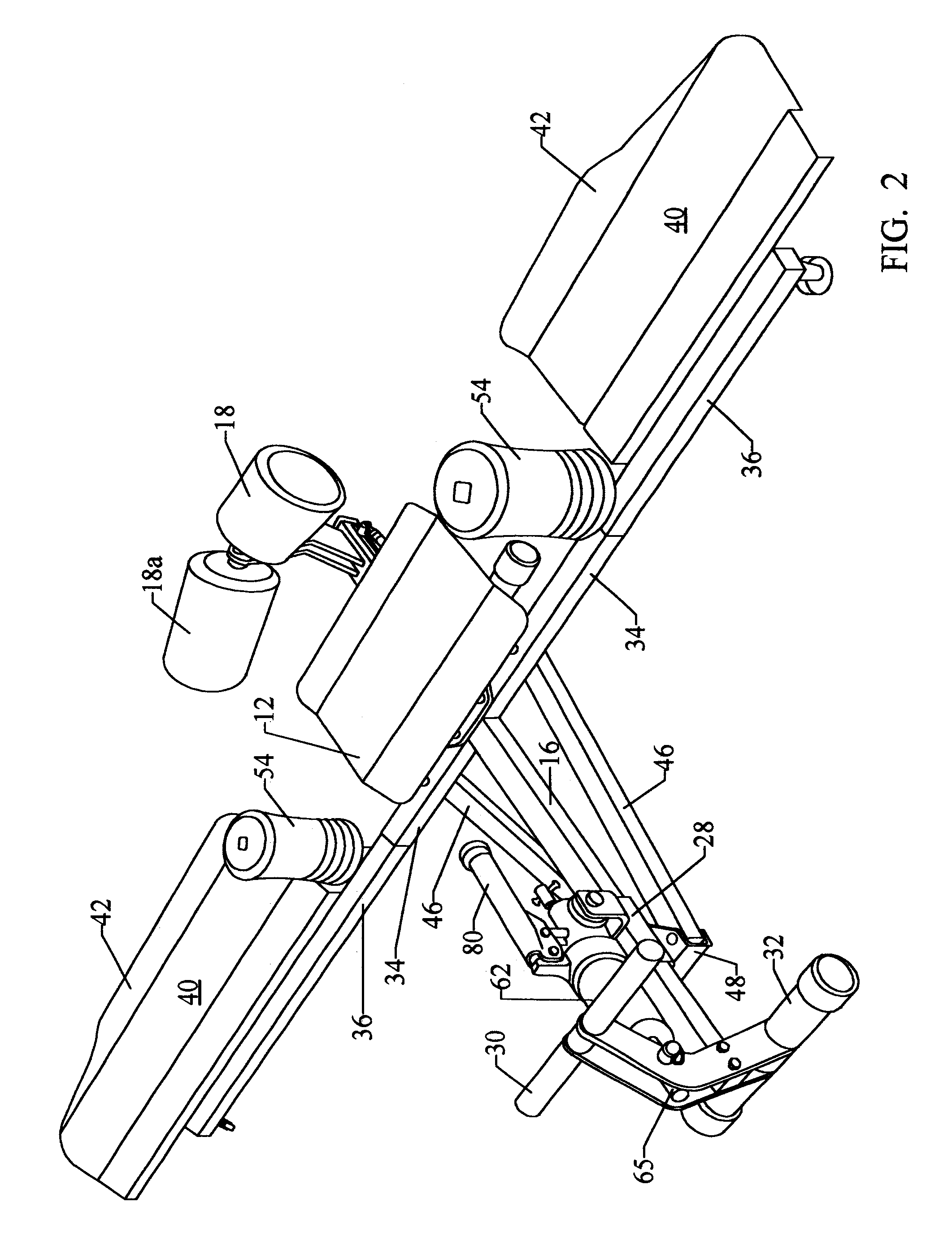
Referring to the drawings, wherein the same reference numerals refer to similar parts throughout the several views, there is shown in FIG. 1 the leg stretching device or machine of my invention indicated generally by the numeral 10. A seat member 12 supported by a bracket 14 is connected to an outwardly extending, horizontal center rail 16 preferably of rectangular configuration as viewed in transverse cross-section on the longitudinal axis. The seat preferably includes a suitable back rest 18 and 18a, such as cylindrical bodies for comfort as illustrated, and desirably formed of a resilient material such as a closed-cell foam or rubber or neoprene. The rollers are supported by a brace 20 attached to a sleeve 22 mounted on the rail behind the seat, and a quick release latch 24 allows for adjusting the position of the back rest. The rail and seat are supported at about opposed ends by suitable legs 26.

A sleeve 28 is slidably mounted near the free end of the rail 16 (that is, opposite...


PUM


Abstract

An exercise device for stretching the legs of a user with pressure being applied mainly at the inner thighs, including a seat member and a horizontally disposed rail mounted at one end to the seat member and extends forwardly therefrom and terminates with a free end. Near the free end of the rail a reciprocating sleeve engages the rail for horizontal adjustment thereon. A leg supporting member is mounted pivotally at one end to the seat member on opposing sides of the rail and each such member has a free end. A linking arm is pivotally connected on opposite sides of the rail and at one end to the rail, and each such arm is connected at opposite end to the leg supporting member. A leg deck is mounted at about the side of each leg supporting member to retain the leg of the user in a horizontal position. An engagement member is mounted on each leg supporting member mediate the seat and the leg deck, and adaptable to engage the inside of the thigh of the user. Actuating cylinder is affixed to the sleeve to pivotally actuate the linking arms upon horizontal adjustment of the sleeve so as to impart an arcuate opening and closing movement to the leg supporting members, whereby pressure is applied on the inside of the user's thigh upon leg stretching movement.

Description

This invention relates to a leg stretching device. In its more specific aspect, this invention relates to an exercise device for the controlled, intermittent muscle stretching of the legs, in particular the adductor muscles of the thighs.BACKGROUND OF THE INVENTION AND PRIOR ARTNumerous exercising devices, apparatuses, or machines are known in the art for stretching the muscles of the body, including the limbs of the body. For this type of machine, the general concept of a leg stretching machine is in wide use. These machines for stretching the leg muscles are designed for improving the flexibility of the user in performing the side splits or spread eagle. Most martial arts require extreme flexibility for superior kicking agility. However, flexible and limber limbs are important in many other sports such as gymnastics, ice skating, and track and field events, and further contribute to the overall good health of the user.In general, these machines or devices comprise a seating arrang...

Claims


Application Information

Patent Timeline
Patent Type & Authority Patents(United States)
IPC IPC(8): A63B21/008A63B23/04A63B22/00A63B22/20
CPCA63B21/0083A63B23/0488A63B21/1492A63B21/00072A63B22/20Y10S482/907A63B21/4047
Inventor BUSSELL, ERNIE L.
Owner BUSSELL ERNIE L
Learn More