Method of manufacturing structural body and structural body

a manufacturing method and structural body technology, applied in the direction of manufacturing tools, soldering devices, auxillary welding devices, etc., can solve the problems of deteriorat degrading the appearance of the vehicle body, and not improving the appearan

Inactive Publication Date: 2004-06-08
HITACHI LTD
View PDF16 Cites 23 Cited by
  • Summary
  • Abstract
  • Description
  • Claims
  • Application Information

AI Technical Summary

Problems solved by technology

Moreover, when welding the vehicle body, the material is heated to a very high temperature, which causes deformation of the surfaces of the vehicle, and thereby deteriorates the appearance thereof.
If the vehicle body is completed by a hairli...

Method used


Image

  • Method of manufacturing structural body and structural body
  • Method of manufacturing structural body and structural body

Examples


Embodiment Construction

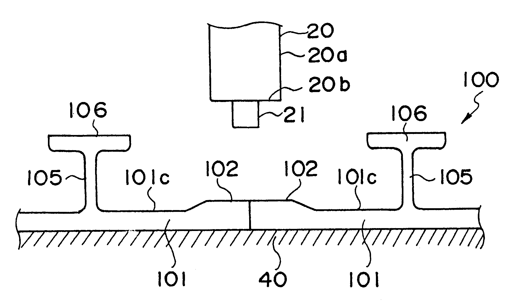
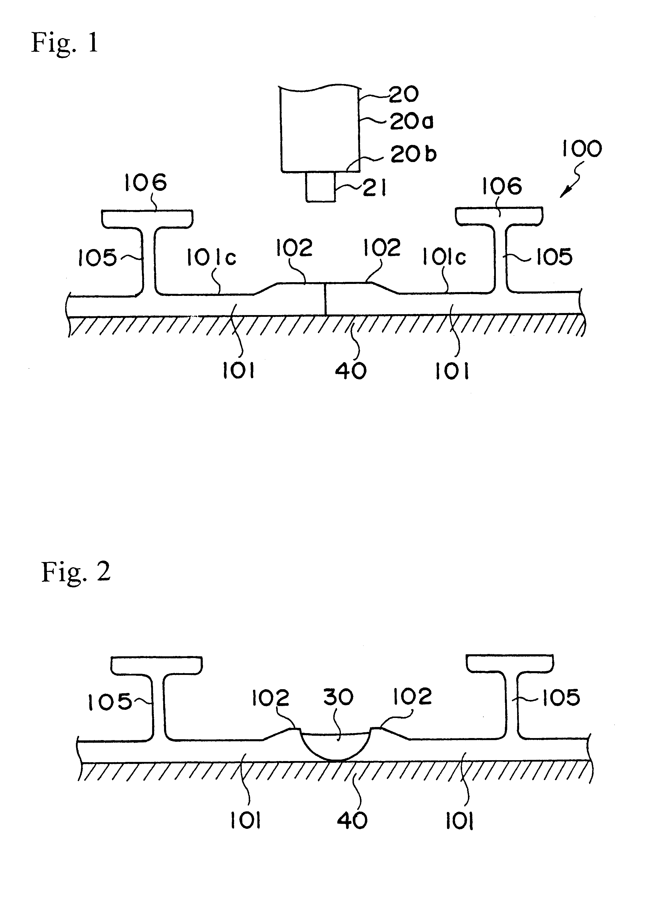
A preferred embodiment of the present invention will now be explained with reference to FIG. 1 and FIG. 2. The present embodiment represents an application of the present invention to the manufacturing of a body of a railway car. The members to be joined together are, for example, extruded members 100 formed of aluminum alloy. The side structure, the roof structure, the gable structure and the floor structure of the vehicle body of the railway car is formed by joining plural extruded members 100 to one another to form a panel or frame. In the case of the side structure, the roof structure and the floor structure, the length of the member 100 is at maximum equal to the length of the vehicle body. The longitudinal direction of the member 100 is positioned in line with the longitudinal direction of the vehicle body. The gable structure defines the end portion of the vehicle body.

The member 100 comprises a face plate 101 and plural ribs 105 formed to extend from one side surface of the ...


PUM

PropertyMeasurementUnit
Thicknessaaaaaaaaaa

Abstract

Plural extrusion members 100, each having plural ribs 105 formed on one surface of a face plate 101, are mounted on a frame 40 with the surface not having the ribs 105 facing downward, and with the end regions of the adjacent members 100, 100 being butted to each other. Then, the end regions of said members 100 are welded using friction stir welding from the upper direction with a rotary body 20, and then a hairline finish is applied to said surface not having the ribs, which constitutes the exterior surface of the vehicle body. In this way, there is substantially no need to cut off the joint bead, which improves the appearance of the vehicle body and reduces the manufacturing cost.

Description

The present invention relates to a method for joining extrusion members through friction stir welding so as to manufacture a structural body, for example a vehicle.DESCRIPTION OF THE RELATED ARTAs disclosed in Japanese Patent Laid-Open Publication No. 9-309164 (EP 0797043A2), a friction stir welding is a technique in which a round shaft (called a rotary body) is rotated and inserted in the joint region of members to be joined, and the rotary body is moved along the junction line, thereby heating, mobilizing and plasticising the material, whereby a solid-phase welding of the members is achieved. The rotary body comprises a small-diameter portion to be inserted into the joint region, and a large-diameter portion to be positioned externally of the joint. The small-diameter portion and the large-diameter portion are coaxial, and the large-diameter side is coupled to a drive source. The boundary between the small-diameter portion and the large diameter portion is partially inserted into ...

Claims


Application Information

Patent Timeline
IPC IPC(8): B23K37/08B61D17/04B23K20/12
CPCB23K20/122B23K37/08B61D17/04Y02T30/34Y02T30/00B23K20/12
Inventor EZUMI, MASAKUNISATOU, AKIHIROFUKUYORI, KAZUSHIGE
Owner HITACHI LTD
Why Eureka
Try Eureka