Light control sheet, surface light source device and liquid crystal display

a technology of surface light source and light control sheet, which is applied in the direction of identification means, instruments, lighting and heating apparatus, etc., can solve the problems of unresolved, no desirable control of output direction, and subject to the direction of subsidiary light flux control

Inactive Publication Date: 2004-06-08
ENPLAS CORP
View PDF3 Cites 93 Cited by
  • Summary
  • Abstract
  • Description
  • Claims
  • Application Information

AI Technical Summary

Benefits of technology

An object of the present invention is to overcome the above problem. In other words, an object of the present invention is to provide a light control sheet that is able to give an well-controlled output direction to light which is inputted from a direction biased to a frontal direction with respect to a main beam.
Another object of the present invention is to provide a surface light source device that is able to have an well-controlled emission directivity by means of the improved light control sheet. And still another object of the present invention is to provide a liquid crystal display that is able to display an image looking bright as viewed from a certain direction.

Problems solved by technology

In other words, there arises a problem with direction control of subsidiary light flux is subject.
To the contrary, regarding the first subsidiary light flux, namely, regarding a light flux that is emitted from the emission face 5 toward a direction nearer to the frontal direction as compared with the main beam, the above problem has not been solved and no desirable control of output direction has been achieved.

Method used


Image

  • Light control sheet, surface light source device and liquid crystal display
  • Light control sheet, surface light source device and liquid crystal display
  • Light control sheet, surface light source device and liquid crystal display

Examples


Embodiment Construction

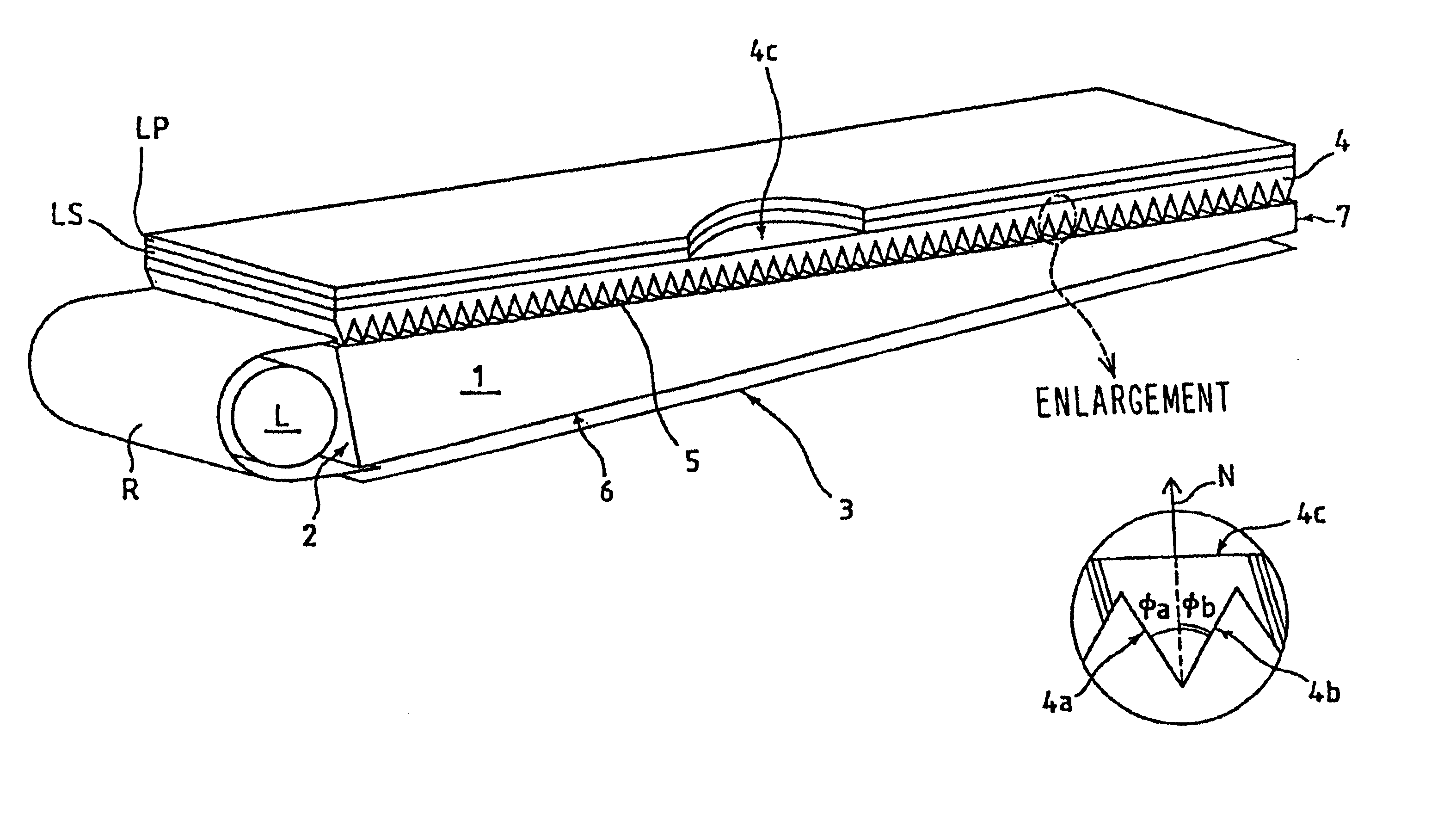
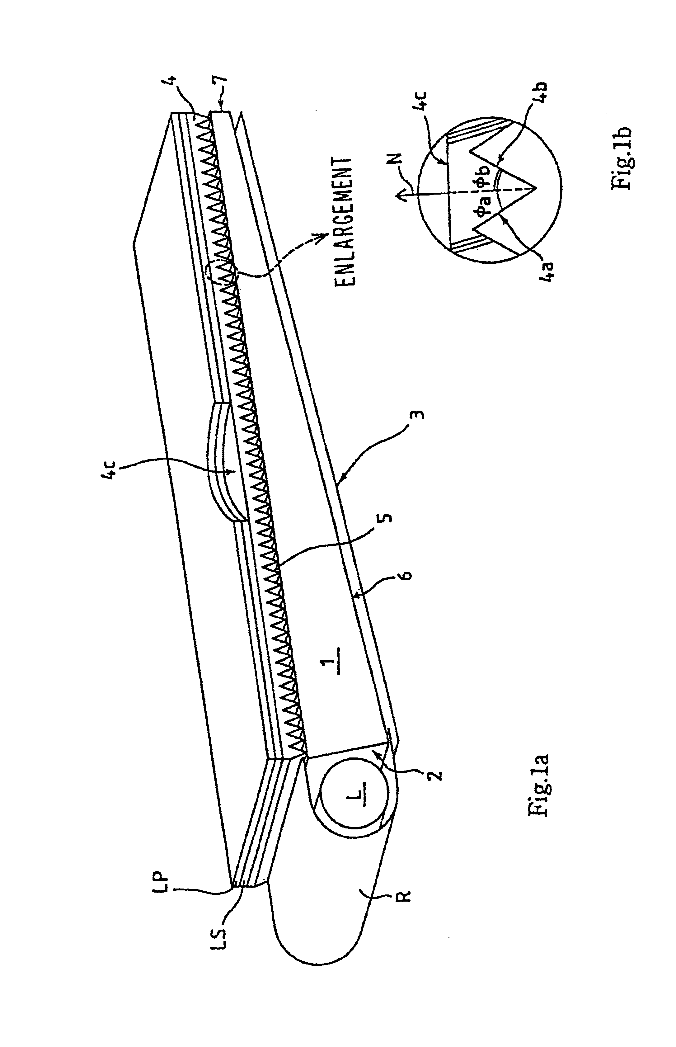
Embodiment of the present invention are described below. In drawings for illustrating outlined structures of the embodiments, thickness of a light control sheet and other elements and factors such as pitch or depth of projection rows are exaggerated for the sake of illustration. Elements shown and denoted by reference symbols in FIGS. 1a, 1b are also denoted by the same reference symbols so far as being used in common.

FIG. 4a is a partially exploded perspective outline view of a first embodiment in accordance with the present invention and FIG. 4b is a partially enlarged cross section view of the embodiment shown in FIG. 4a. This embodiment is, although being structured in a similar way as compared with the conventional liquid crystal display shown in FIGS. 1a and 1b, different from the conventional liquid crystal display in that a light control sheet 41 featured by the present invention is disposed along an emission face 5 of a light guide plate 1 instead of the prism sheet 4.

The l...


PUM

PropertyMeasurementUnit
emission angleaaaaaaaaaa
vertical angleaaaaaaaaaa
angle θ2aaaaaaaaaa

Abstract

A light control sheet suitable for direction-controlling an angularly extending oblique input light, surface light source device and LCD using the light control sheet. A light control sheet is disposed along an emission face of a light guide plate direction-controls main and subsidiary light fluxes to cause them to be emitted toward a desired direction. Main beam S1 emitted from the emission face transmits (with a small refraction) through a first face, being inner-reflected (total reflection) by a first slope region and then outputted from a light output face (SS1). First subsidiary beam T1 transmits (with a small refraction) through the first face, being inner-reflected (total reflection) by a second slope region and then outputted from the light output face (TT1).

Description

1. Field of InventionThe present invention relates to a light control sheet to direction-control an angularly extending light inputted from an oblique direction so that an output light is directed to an desired direction, also relating to a surface light source device and LCD using the light control sheet. The present invention is applicable to general light controls and various devices which require an illumination light extending like a face, for example, display incorporated in a personal computer or car navigation system.2. Related ArtA proposed surface light source device employs a light guide plate made of a transparent light guiding material or light scattering-guiding material and a prism sheet, being broadly applied to various uses such as backlighting of liquid crystal display. A prism sheet is a most popular light control sheet which is used for direction-control an obliquely inputted light so that an output light is directed to an desired direction. A prism sheet is made...

Claims


Application Information

Patent Timeline
Patent Type & Authority Patents(United States)
IPC IPC(8): F21V8/00G02B6/00G02B6/42G02B5/02G02B5/04G02F1/13357G09F9/00
CPCG02B6/0031G02B6/0046G02B6/005G02B6/0053G02B6/0071G02B6/0001G02B6/4298
Inventor OHKAWA, SHINGO
Owner ENPLAS CORP
Why Eureka
Try Eureka