
Weight sensor assembly with overload spring

a sensor and overload spring technology, applied in the direction of pedestrian/occupant safety arrangement, instruments, tractors, etc., can solve the problems of small gap size, difficult to achieve and maintain small gap size, and seat separation from vehicle floor

Inactive Publication Date: 2004-07-06
SIEMENS VDO AUTOMOTIVE CORP
View PDF20 Cites 11 Cited by
  • Summary
  • Abstract
  • Description
  • Claims
  • Application Information

AI Technical Summary

Benefits of technology

This configuration enhances the sensor assembly's deflection range, preventing permanent deformation and improving accuracy, allowing for effective weight measurement and overload protection with larger gap sizes, thus addressing the limitations of prior systems.

Problems solved by technology

This upward force can cause the seat to separate from the vehicle floor.
One disadvantage with the current system is that during an overload condition, the bendable body portion can plastically deform or break, resulting in permanent damage to the sensor assembly.
This small gap size is difficult achieve and maintain due to dimensional tolerance stack-ups resulting from the assembly of various different components.
Another disadvantage with the current system is that due to the structural mounting configurations and requirements for overload protection in seat assemblies, it is difficult to provide adequate strength for the body portion of the sensor while also providing accurate strain measurements at the lower strain ranges.

Method used


Image

  • Weight sensor assembly with overload spring
  • Weight sensor assembly with overload spring
  • Weight sensor assembly with overload spring

Examples


Embodiment Construction

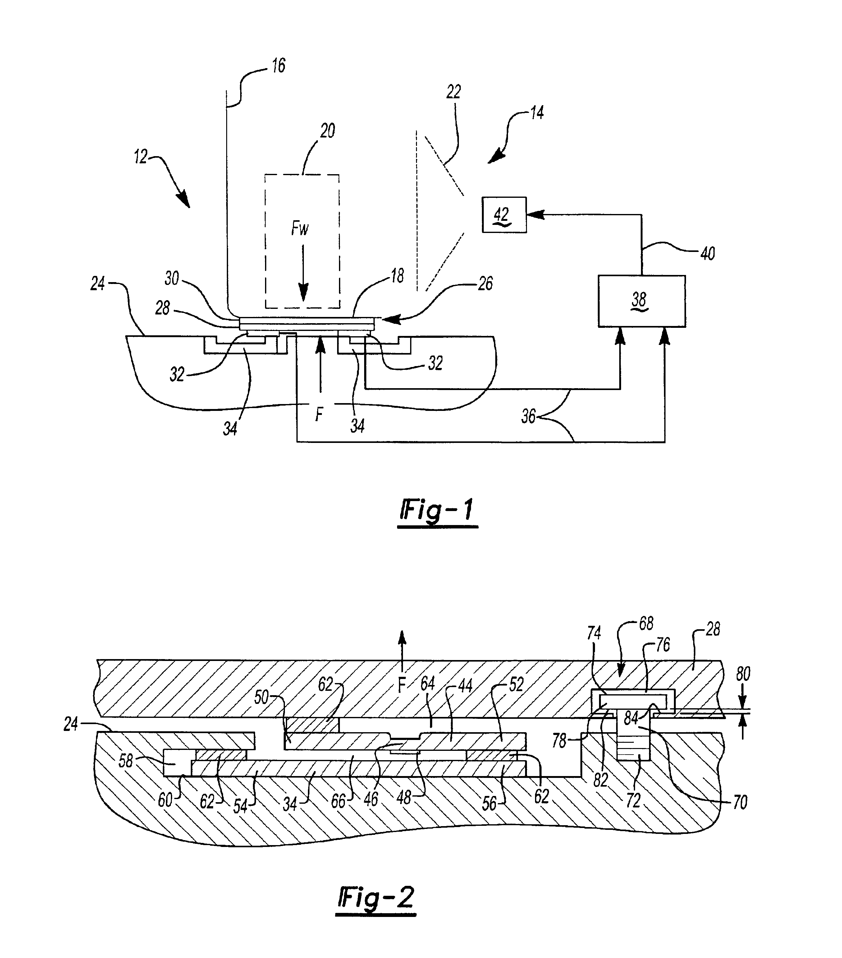
A vehicle includes a vehicle seat assembly, shown generally at 12 in FIG. 1, and an airbag system 14. The seat assembly 12 can be either a driver or passenger seat and includes a seat back 16 and a seat bottom 18. When a vehicle occupant 20 is seated on the seat 12 a weight force Fw is exerted against the seat bottom 18. The weight force Fw represents the weight of the seat occupant 20. The seat occupant 20 can be a large adult, a small adult, a child, an infant seat, or some type of package or other object.

The airbag system 14 deploys an airbag 22 under certain collision conditions. The deployment force for the airbag 22, shown in dashed lines in FIG. 1, varies according to the weight of the occupant 20. The vehicle includes a unique system for measuring the weight of the seat occupant 20, which includes overload protection.

The seat 12 is preferably mounted to vehicle base member 24 such as a riser or vehicle floor with a track assembly 26 to allow horizontal seat adjustment. The t...


PUM


Abstract

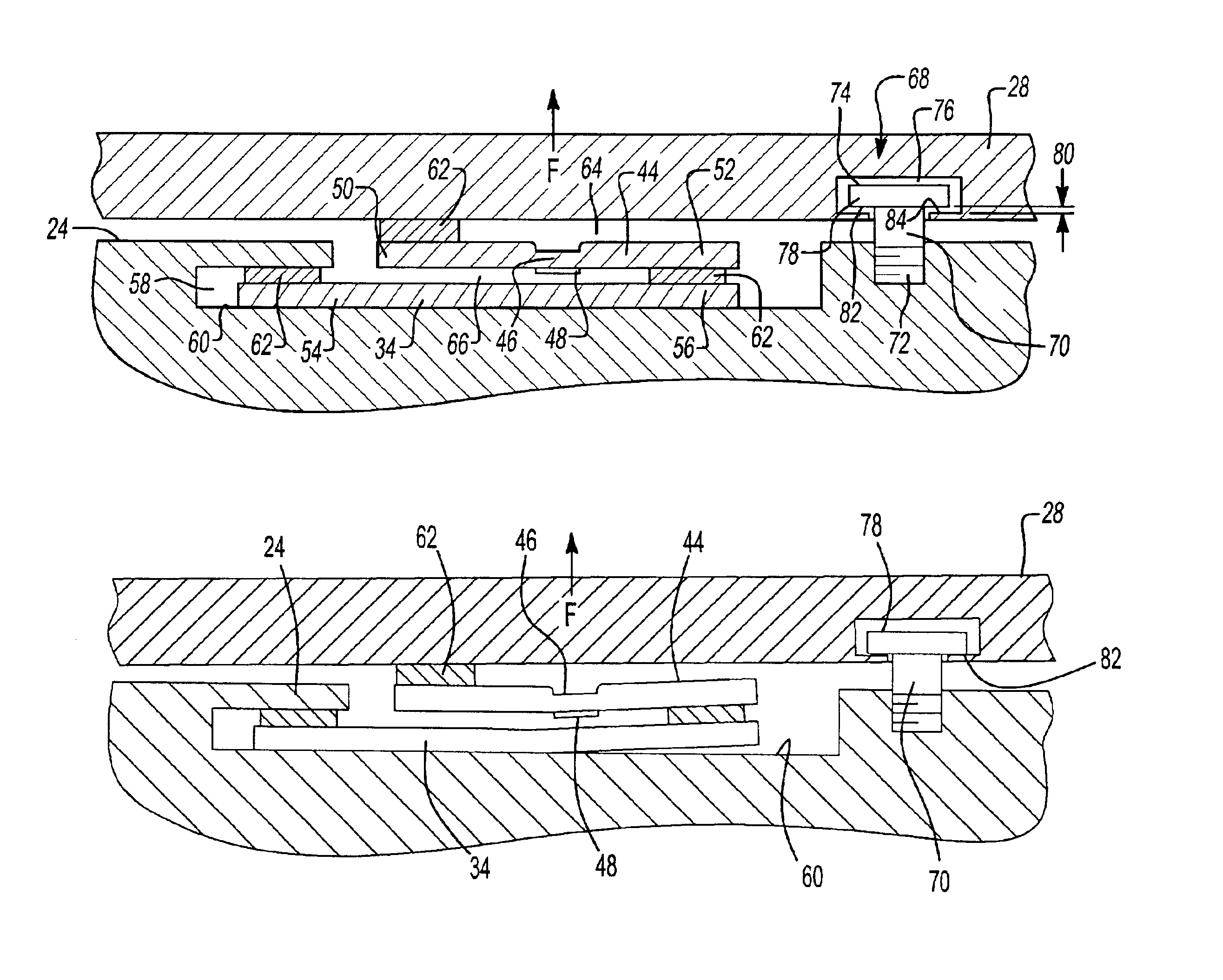
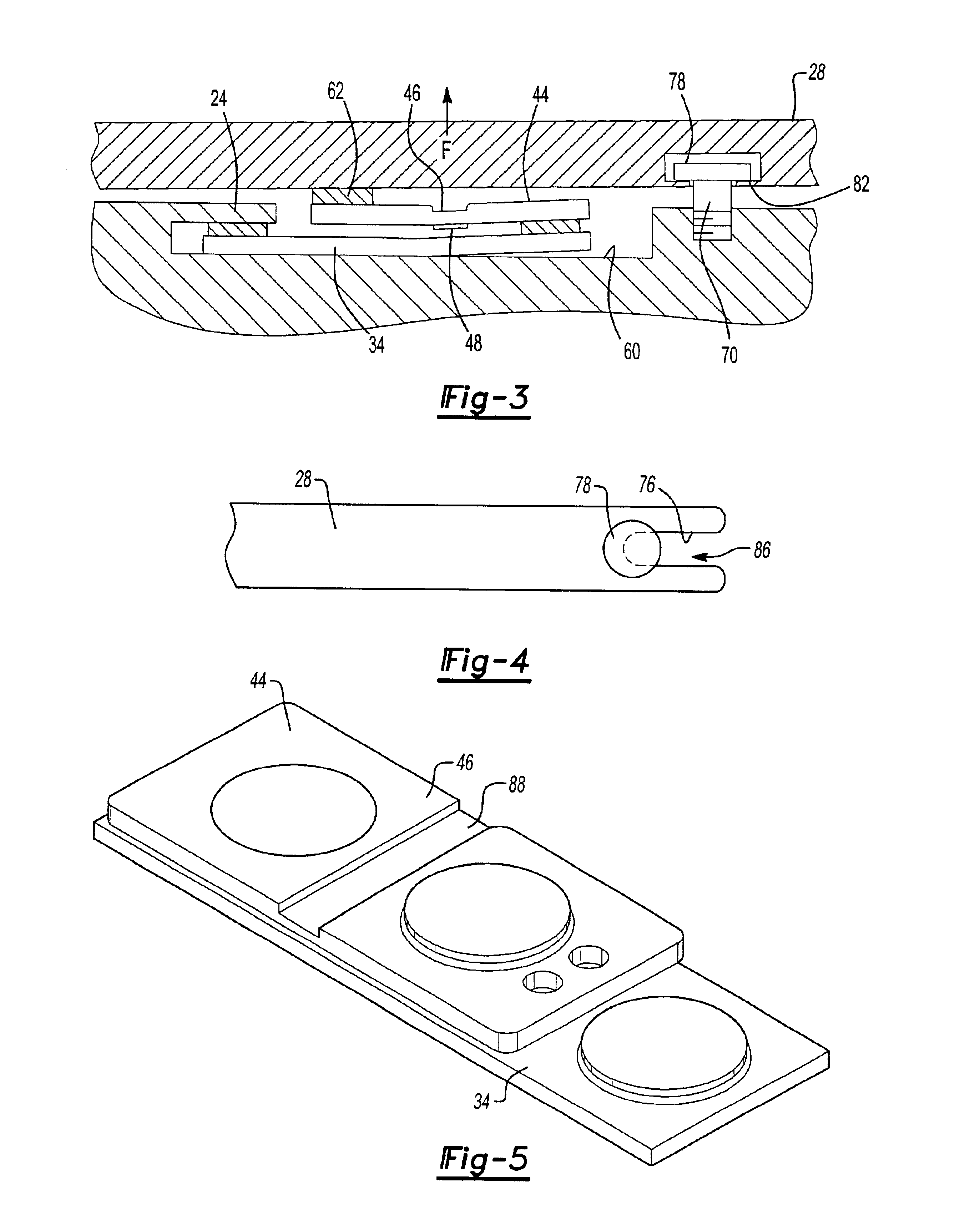
A vehicle seat assembly 12 is mounted to a vehicle base member 24 such as a riser or a vehicle floor. Weight sensor assemblies 32 for measuring weight on the vehicle seat are mounted to a seat structural component. The weight sensor assemblies 32 each include plate 44 having a bendable center body portion 46 for supporting a strain gage 48. The strain gage 48 measures bending in the center body portion 46 caused by normal weight force applications on the vehicle seat 12. A secondary resilient beam member 34 is mounted between each weight sensor 32 and the vehicle base member 24. The beam member 34 and the weight sensors 32 deflect to prevent failure of the weight sensors 32 in response to an overload force applied in an opposite direction to the direction of a normal weight force application. The beam member 34 prevents permanent deformation of the plate 44 and strain gage failure by allowing the weight sensor 32 to deflect upwardly away from the vehicle floor. An overload stop 68 reacts between the seat structural component and the vehicle floor to prevent seat separation under overload conditions.

Description

1. Field of the InventionThis invention relates to a sensor assembly for measuring the weight applied to a vehicle seat.2. Related ArtMost vehicles include safety devices such as airbags and seatbelt restraint systems, which work together to protect the driver and passengers from experiencing serious injuries due to high-speed collisions. It is important to control the deployment force of the airbags based on the size of the driver or the passenger. When an adult is seated on the vehicle seat, the airbag should be deployed in a normal manner. If there is an infant seat or small adult / child secured to the vehicle seat then the airbag should not be deployed or should be deployed at a significantly lower deployment force. One way to control the airbag deployment is to monitor the weight of the seat occupant.One system for measuring seat occupant mounts sensors between various structural components on a vehicle seat, such as between an upper seat structural component and a seat riser or...

Claims


Application Information

Patent Timeline
Patent Type & Authority Patents(United States)
IPC IPC(8): B60R21/01G01G19/40G01G19/414B60R21/015
CPCG01G19/4142B60R21/01516Y10S177/09
Inventor CURTIS, BRIAN M.CLARK, JEFFREY A.
Owner SIEMENS VDO AUTOMOTIVE CORP
Learn More