Routing display for navigation systems

a navigation system and display technology, applied in navigation instruments, surveying and navigation, instruments, etc., can solve the problem of only being registered by the driver with difficulty

Inactive Publication Date: 2004-07-13
CONTINENTAL AUTOMOTIVE GMBH
View PDF18 Cites 44 Cited by
  • Summary
  • Abstract
  • Description
  • Claims
  • Application Information

AI Technical Summary

Problems solved by technology

However, a problem with this indication is that it can be registered by the driver only with difficulty during the journey.

Method used


Image

  • Routing display for navigation systems
  • Routing display for navigation systems

Examples


Embodiment Construction

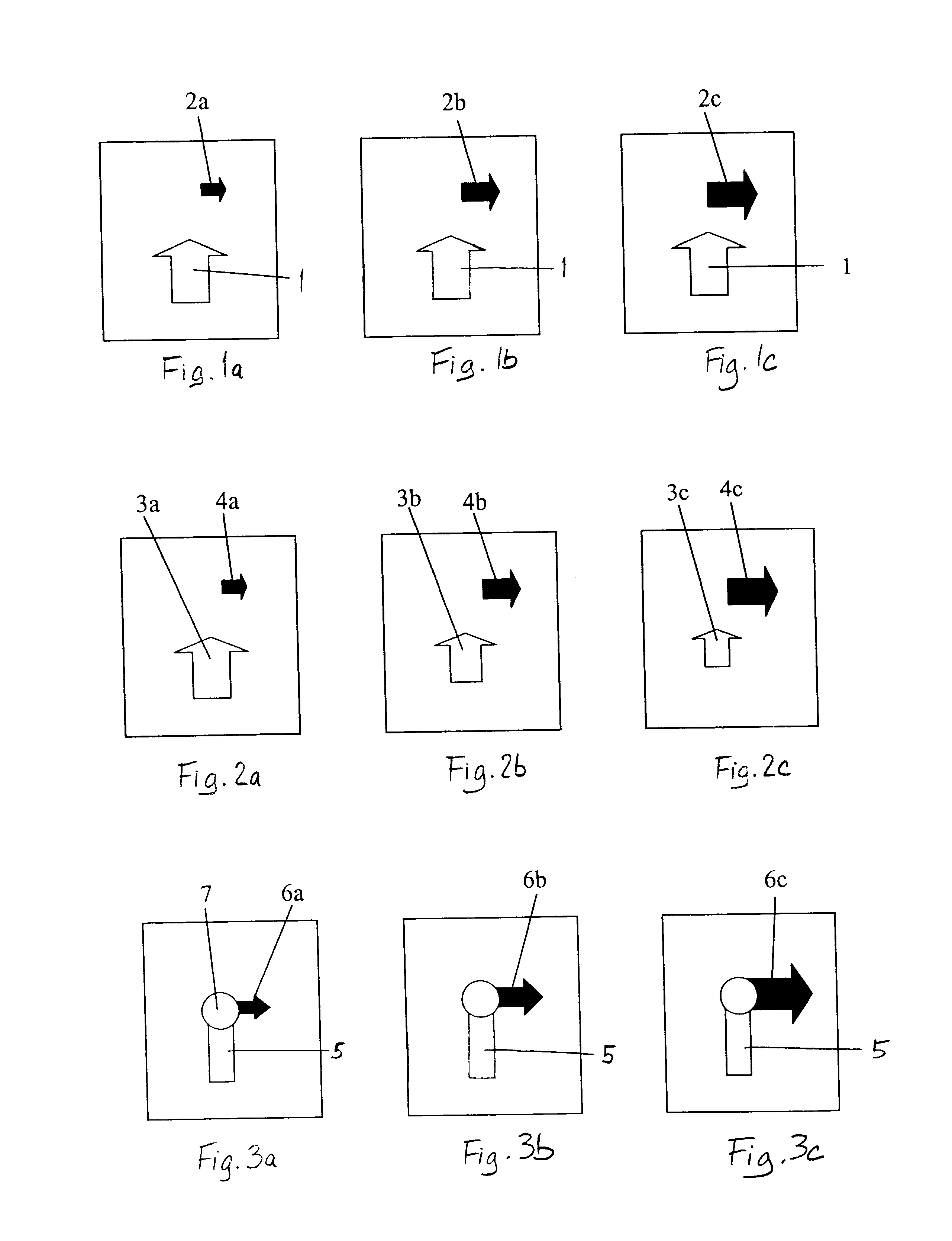
FIGS. 1a, 1b, and 1c show a first routing display having three different representations for three different distances to the turn-off point. These routing displays are an advance warning type instruction. As the vehicle comes closer to the turn-off point than a certain prescribed minimum distance the display changes over to a more detailed representation of the turn-off point and of the directions of travel which are to be taken, as is known from the aforementioned prior art. In the representation shown in FIG. 1a, the vehicle is at a first distance from the turn off point which is a furthest distance away from the turn-off point. In FIG. 1b, the vehicle is at a second distance which is closer to the turnoff point and in FIG. 1c the vehicle is at a third distance which is closest to the turn-off point. In FIGS. 1a, 1b, 1c, an arrow 1 indicates the current direction of travel of the vehicle. The size and position of the arrow 1 remain independent of the distance to the next turn-off...


PUM


Abstract

A routing display for a navigation system in a road vehicle in the form of an electro-optical display can be driven by a routing computer and uses symbols to display a direction of current travel and a direction which is to be taken after a turn-off point relative to one another. The sizes of the two symbols relative to one another is changed such that the relative size of the symbol marking the direction which is to be taken after the turn-off point increases as the turn-off point is approached. Accordingly, when the driver looks at the routing display, he is given the visual impression that he is approaching the turn-off point.

Description

1. Field of the InventionThe invention relates to a routing display for a navigation system in a road vehicle in the form of an electro-optical display that is drivable by a routing computer, and which is able to use symbols to display a direction of current travel and a direction which is to be taken after a turn-off point relative to one another. The invention also relates to a method for showing routing information.2. Description of the Related ArtIn navigation systems, routing is carried out by outputting routing information via an audio or visual output unit. It has been found to be particularly useful for the visual display of routing information to show arrows which indicate to the driver the direction in which he needs to turn off at the next turn-off point. It is of particular importance that the driver receive an indication of whether this turn-off maneuver is immediately imminent or whether it is only needed after a relatively long distance in addition to the pure turn-of...

Claims


Application Information

Patent Timeline
Patent Type & Authority Patents(United States)
IPC IPC(8): G01C21/34G01C21/36G01C21/00G08G1/0969
CPCG01C21/3632
Inventor HULVERSCHEIDT, JURGENSCHOTT, JOACHIM
Owner CONTINENTAL AUTOMOTIVE GMBH
Why Eureka
Try Eureka