Piston type compressor

a compressor and piston technology, applied in the field of compressors, can solve the problems of low responsiveness and the inability to increase and achieve the effect of improving the efficiency of the intake valve with refrigeran

Inactive Publication Date: 2004-07-27
CALSONIC KANSEI CORP
View PDF7 Cites 12 Cited by
  • Summary
  • Abstract
  • Description
  • Claims
  • Application Information

AI Technical Summary

Problems solved by technology

However, due to inherent construction, the reed valve elements of the above-mentioned type tend to lower the responsiveness thereof.
If such delay is not small, satisfied increase in refrigerant intake efficiency of the intake valves is not expected.

Method used


Image

  • Piston type compressor
  • Piston type compressor
  • Piston type compressor

Examples


first embodiment

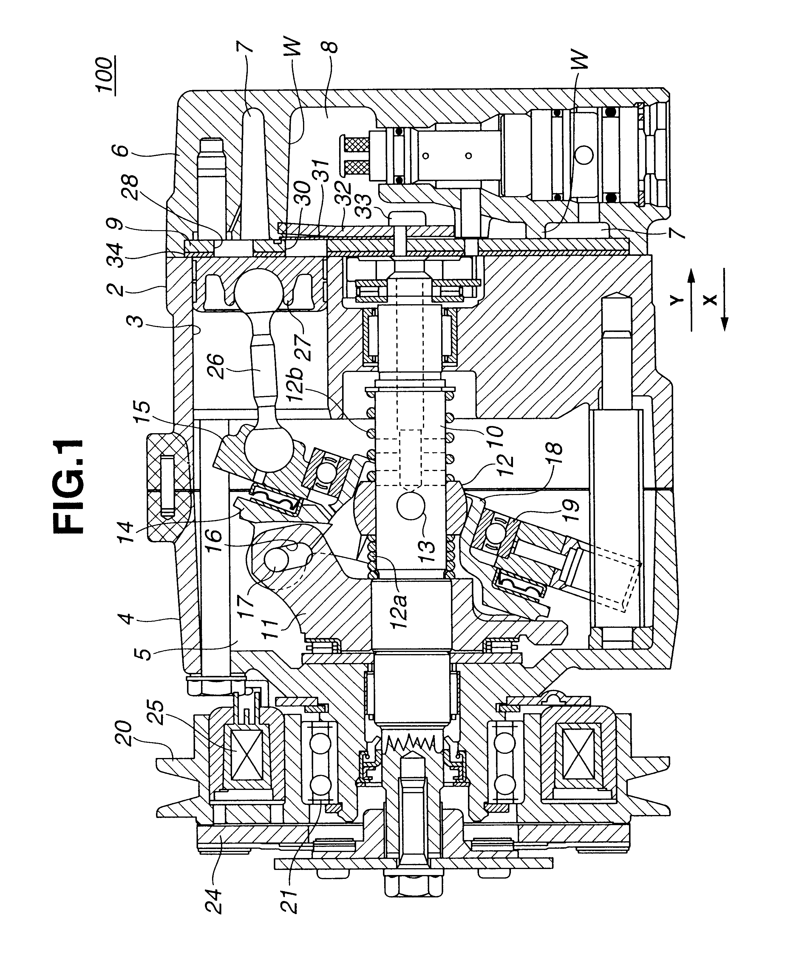
Referring to FIGS. 1 to 7, particularly FIG. 1 of the drawings, there is shown a wobble plate piston type compressor 100 which is the present invention. As shown, the compressor 100 is of a so-called single head type.

As is best shown in FIG. 1, the compressor 100 comprises a cylinder block 2 in which six cylindrical piston bores 3 are arranged circularly, a front housing 4 attached to a left end face of the cylinder block 2 to define therebetween a crank chamber 5 and a rear housing 6 attached to a right end face of the cylinder block 2 having a circular valve base plate 9 disposed therebetween.

The rear housing 6 has therein both an annular intake chamber 7 and a circular discharge chamber 8 which are parted by a generally circular wall W. As is understood from FIG. 3, the annular intake chamber 7 is arranged to surround the circular discharge chamber 8.

Referring back to FIG. 1, within the crank chamber 5, there extends a drive shaft 10. A drive plate 11 is fixed to the drive shaft ...

second embodiment

Referring to FIG. 9, there is shown a reed valve element 40 that is employed in a wobble plate piston type compressor 200 of the present invention.

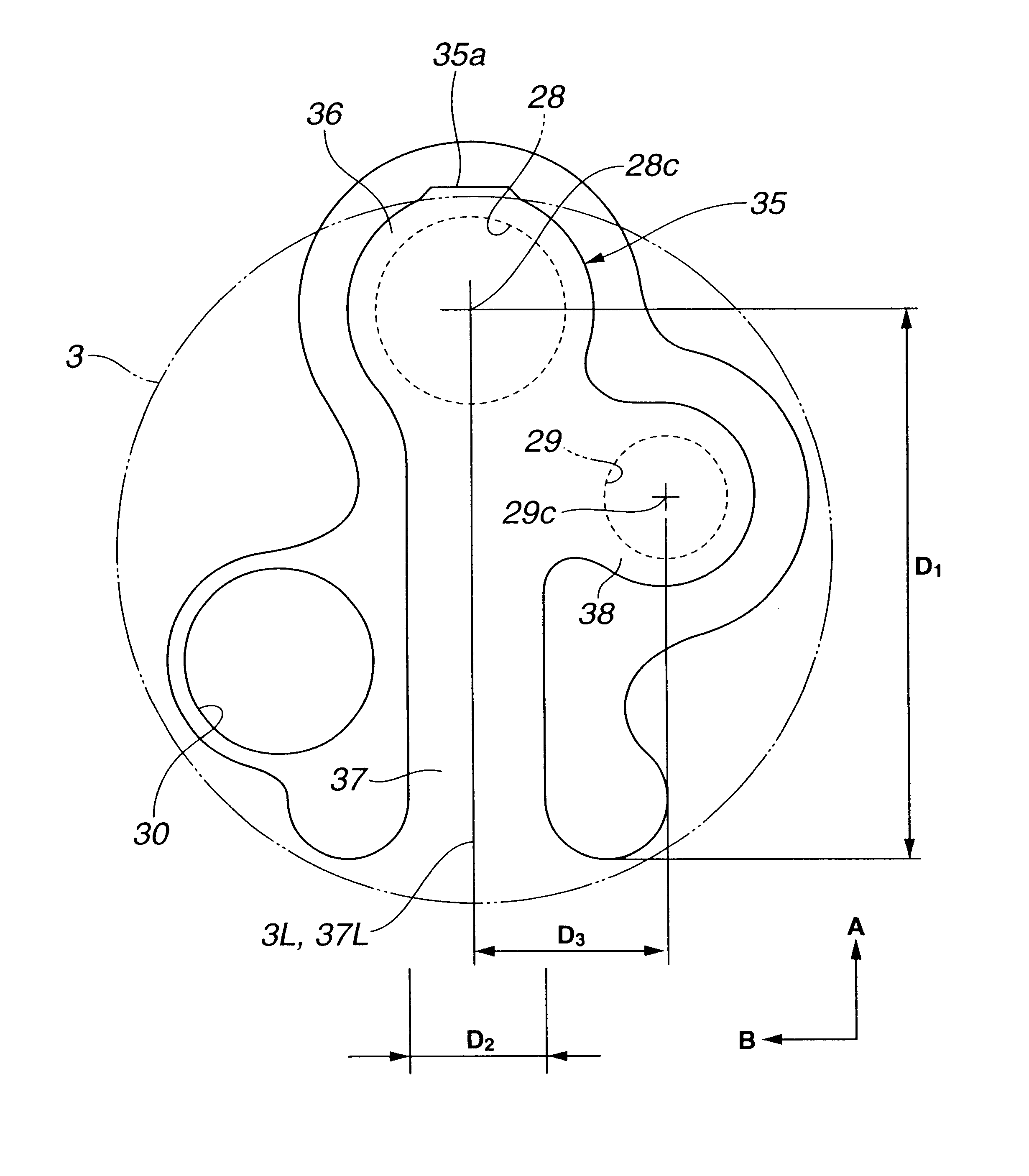
As shown, in this second embodiment 200, the reed valve element 40 has a symmetrical shape. That is, the reed valve element 40 comprises an elastic arm portion 37 whose center line 40L is consistent with a diametrical center line 3L of the cylindrical piston bore 3. As shown, the elastic arm portion 37 is so sized as to cover both the first and second intake openings 28 and 29. In other words, the first and second valve element parts 36 and 38 for opening and closing the first and second intake openings 28 and 29 are both included in the elastic arm portion 37. Denoted by numeral 40a is a leading end of the elastic arm portion 37, that is engageable with the stopper recess 39.

As is seen from the drawing, the second valve element part 38 is placed at an offset position relative to the center line 40L. The offset degree D3 of the second val...

third embodiment

Referring to FIG. 10, there is shown a reed valve element 41 that is employed in a wobble plate piston type compressor 300 of the present invention.

As shown, in this third embodiment 300, the center line 41L of the elastic arm portion 37 of the reed valve element 41 is placed at an offset position relative to the diametrical center line 3L of the cylindrical piston bore 3. The center 28c of the first intake opening 28 is consistent with the center line 41L, and the center 29c of the second intake opening 29 is consistent with the diametrical center line 3L. Denoted by numeral 41a is the leading end of the elastic arm portion 37, that is engageable with the stopper recess 39. In this third embodiment 300, the twisting of the reed valve element 41 is much assuredly made when the leading end 41a of the arm portion 37 is received by the stopper recess 39.


PUM


Abstract

Between a cylinder block and a housing, there is disposed a valve base plate. The valve base plate is formed with mutually isolated first and second intake openings for fluidly communicating each of piston chambers in the cylinder block with an intake chamber defined in the housing. A reed valve element is incorporated with each piston chamber. The reed valve element is arranged to open the first and second intake openings with the aid of a fluid when the piston is moved away from the reed valve element and close the first and second intake openings with the aid of the fluid when the piston is moved toward the reed valve element. Due to provision of the two, viz., first and second intake openings, opening movement of the reed valve element is carried out along with a twisting motion of the same.

Description

1. Field of the InventionThe present invention relates in general to compressors and more particularly the compressors of a piston type that is widely used in a cooling system of automotive air conditioners.2. Description of the Related ArtIn order to clarify the task of the present invention, a piston type compressor disclosed in Laid-open Japanese Patent Application (Tokkai-hei) 9-280168 will be briefly described. In fact, the compressor of this publication is of a so-called wobble plate piston type that has a wobble plate for inducing reciprocating movement of pistons.The compressor of the publication generally comprises a cylinder block in which a plurality of cylindrical piston bores are circularly arranged. The cylindrical piston bores accommodate respective pistons actuated by a wobble plate. A housing is attached to one end face of the cylinder block having a valve base plate disposed therebetween. The housing has an intake chamber defined therein. The valve base plate is fo...

Claims


Application Information

Patent Timeline
Patent Type & Authority Patents(United States)
IPC IPC(8): F04B39/10F04B27/10F04B27/08
CPCF04B39/108Y10T137/7839Y10T137/784Y10T137/7892Y10T137/7891F04B39/10F16K15/1402F16K15/162F16K15/16
Inventor HIROSE, RYUICHINADAMOTO, HIROYASU
Owner CALSONIC KANSEI CORP
Why Eureka
Try Eureka