
Child-proof electrical outlet plate

a technology of electrical outlet plate and childproof, which is applied in the direction of coupling device connection, coupling/disconnecting parts, electrical apparatus, etc., can solve the problems of easy misplacement of magnet that unlocks the door, large, expensive, and difficult to use, and achieves the effect of preventing the magnet from being damaged, easy to lose keys, and easy to us

Inactive Publication Date: 2004-08-24
VALLS DAVID JOHN
View PDF11 Cites 19 Cited by
  • Summary
  • Abstract
  • Description
  • Claims
  • Application Information

AI Technical Summary

Problems solved by technology

These are large, expensive, and difficult to use.
The key can be lost or the magnet that unlocks the door can be easily misplaced.
These work well in that aspect, but they do not prevent an electrical plug from being pulled out part-way or completely by a curious toddler.
They also do not prevent electric plugs from accidently being pulled out by adults, children, and pets.
The electric outlet has to be replaced and a homeowner may not be skilled enough to do the required electric wiring.
It cannot keep the electric plug from being pulled out.
Objects can not be inserted into vacant electric outlets, since the shutter blocks the opening.
Toddlers can not unlock the shutter because the locks are on the far sides of the cover, too far for a toddler's small hand to unlock both locks at the same time.

Method used


Image

  • Child-proof electrical outlet plate
  • Child-proof electrical outlet plate
  • Child-proof electrical outlet plate

Examples


Embodiment Construction

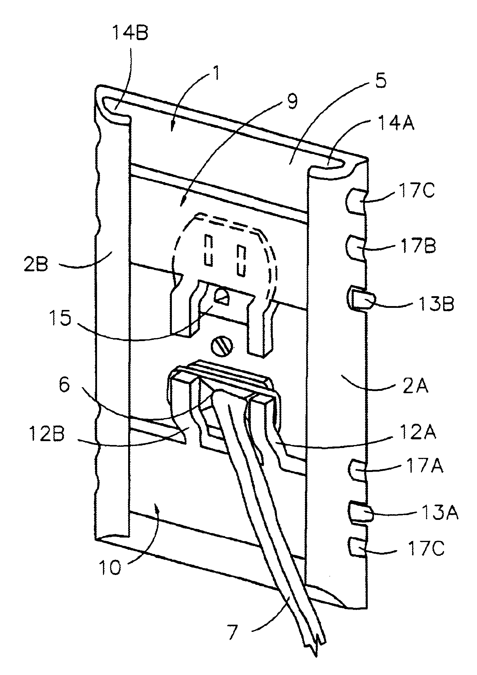
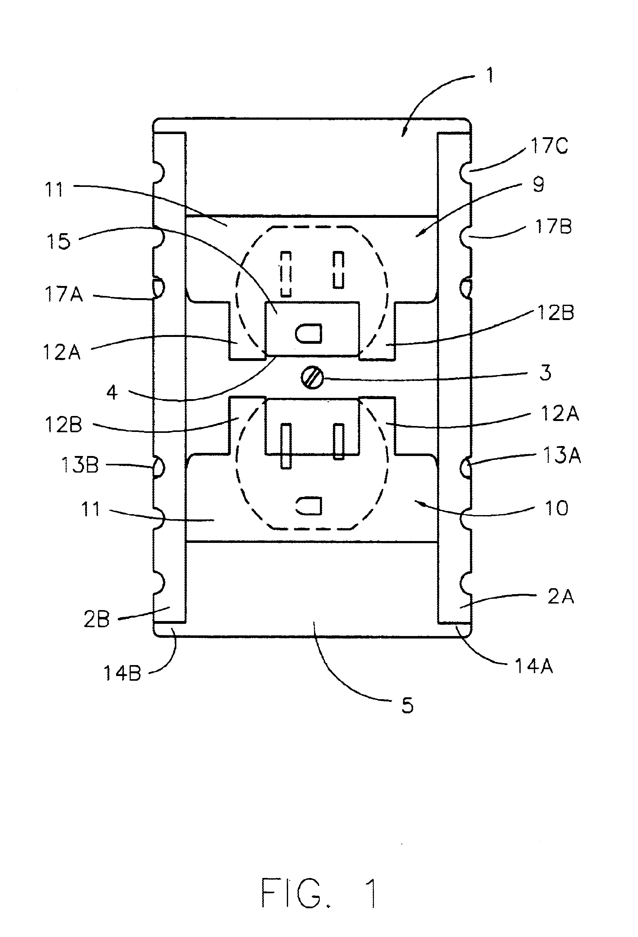
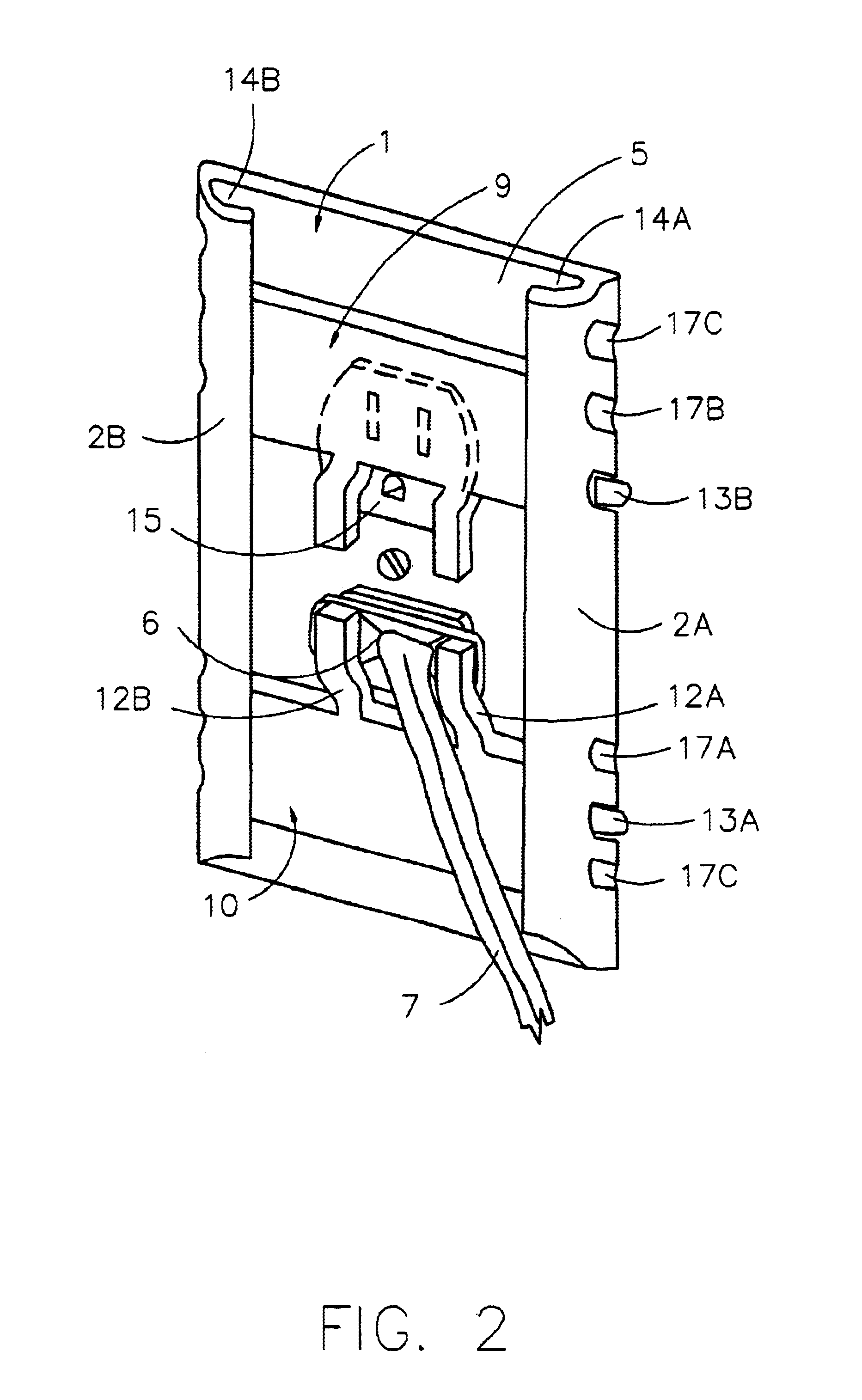
Refer now to FIG. 1 which shows a front view of a safety outlet plate 1 attached to an electric receptacle 15, by a screw in screw hole 3. The safety outlet plate 1 has an upper shutter 9 and lower shutter 10 that can slide up and down along the face 5 of the plate 1. Each shutter is the same. Each shutter 9 and 10 has a right prong 12A and left prong 12B attached to one side. The prongs on each shutter are generally parallel to each other, and the prongs from the upper shutter 9 and lower shutter 10 are generally opposite each other. The shutters 9 and 10 can slide up and down along the right rail 2A and left rail 2B. The shutters are locked into position by a right lever 13A and a left lever 13B.

FIG. 1 shows the upper shutter 9 and lower shutter 10 locked in a closed position. Both shutters are shown covering the live electric outlets of an electric receptacle 15. In the locked position, nothing can be inserted into the live electric contacts of the electric receptacle 15 by a cur...


PUM


Abstract

A safety plate assembly that can be easily assembled to a conventional electric outlet using standard mounting methods. The safety plate assembly has openings for accommodating standard electric outlets. The assembly includes a cover plate with parallel guides. A slidable shutter slides along the parallel guides to cover and uncover the live openings of an electric outlet. The shutter has prongs that hold an electric plug into the electric outlet so the plug cannot be unintentionally removed. The assembly has locks on opposite sides of the slidable shutter, so that the small hand of a toddler cannot unlock both locks at the same time. The shutter can be locked into an open, closed, or holding position.

Description

This invention is an innovative electrical outlet plate that easily replaces standard electric outlet plates. When installed, electric plugs cannot be pulled out by curious toddlers, nor can children insert objects into vacant outlets. Electric plugs from sensitive equipment, like computers, cannot be accidently pulled from the electric outlet by clumsy adults or pets.Since electrical contacts of a conventional electric outlet are continuously energized, they represent a source of danger for electric shocks and short circuits. While the prongs of an electrical outlet are designed to be safely inserted within the outlet sockets, it is possible to cause a short circuit by insertion of a wire or other metal object into the sockets. Specifically, small children are frequent explorers, and out of curiosity, insert articles such as safety pins, hair pins, or paper clips into the outlet with resultant shock and possible injury.Ground Fault Interrupters or GFI's automatically shut off power...

Claims


Application Information

Patent Timeline
IPC IPC(8): H01R13/44H01R13/453H01R13/639
CPCH01R13/4534H01R13/6397H02G3/14
Inventor VALLS, DAVID JOHN
Owner VALLS DAVID JOHN
Learn More