
Pump capable of releasing excessive air

a technology of excessive air and pressure, applied in the field of pressure, can solve the problems of inconvenient removal of the nozzle 90 from the tire valve, inability to release excessive air from the tire, and render precise pumping more difficult, etc., and achieve the effect of convenient operation and convenient touch

Inactive Publication Date: 2004-11-09
SPECIALIZED BICYCLE COMPONENTS INC +1
View PDF6 Cites 27 Cited by
  • Summary
  • Abstract
  • Description
  • Claims
  • Application Information

AI Technical Summary

Benefits of technology

According to the present invention, a pump capable of releasing excessive air is shown to include a hollow base, a cylinder installed on and communicated with the hollow base, a piston movably received in the cylinder, a piston tube including a lower end connected with the piston and an upper end located beyond the cylinder, a tube including a lower end communicated with the hollow base and an upper end inserted into the piston tube through a channel defined in the piston, a release valve mounted on the upper end of the piston tube and a handle mounted on the upper end of the piston tube. The valve is installed on the handle so that it can be touched conveniently and operated easily by a user who is using the pump.

Problems solved by technology

Such releasing excessive air from the tire is not possible unless the nozzle 90 is removed from a valve of the tire.
Such removal of the nozzle 90 from the valve of the tire is however inconvenient.
This renders precise pumping more difficult.

Method used


Image

  • Pump capable of releasing excessive air
  • Pump capable of releasing excessive air
  • Pump capable of releasing excessive air

Examples


Embodiment Construction

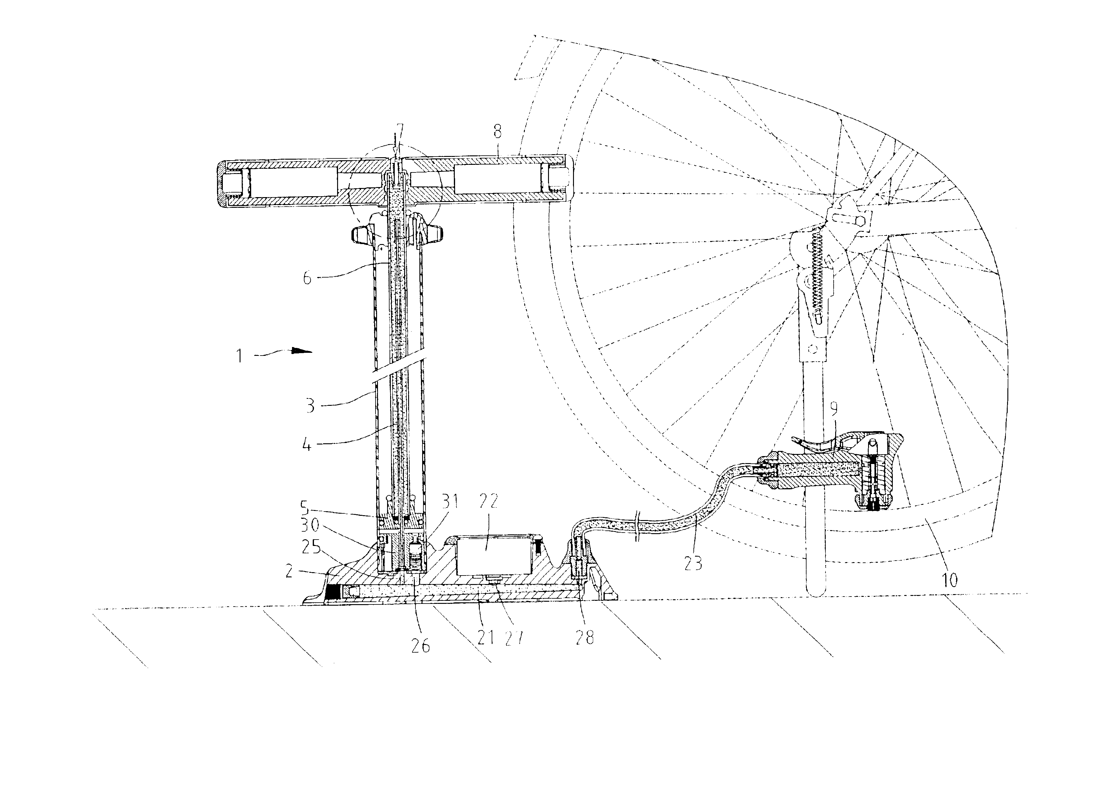
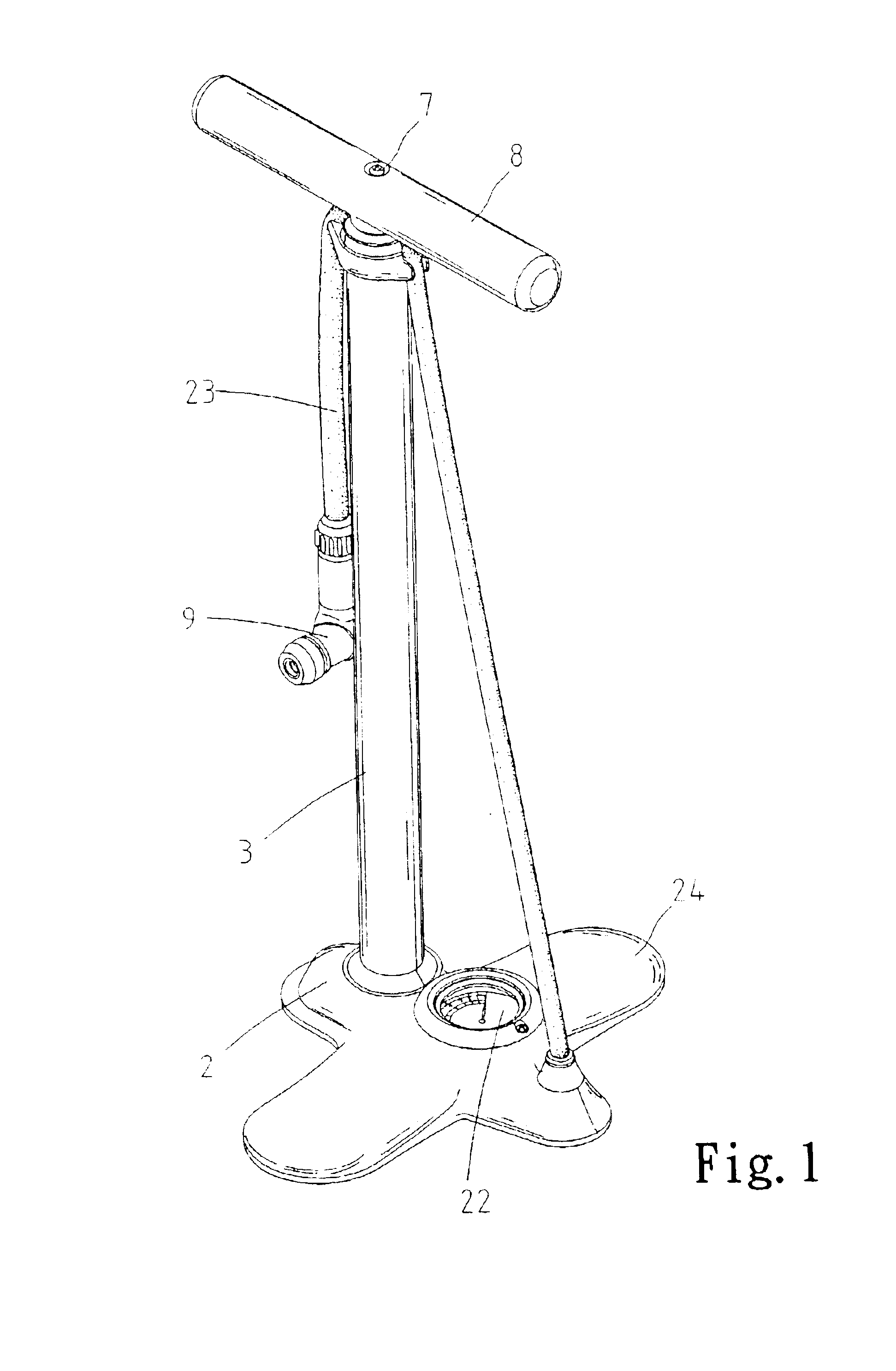
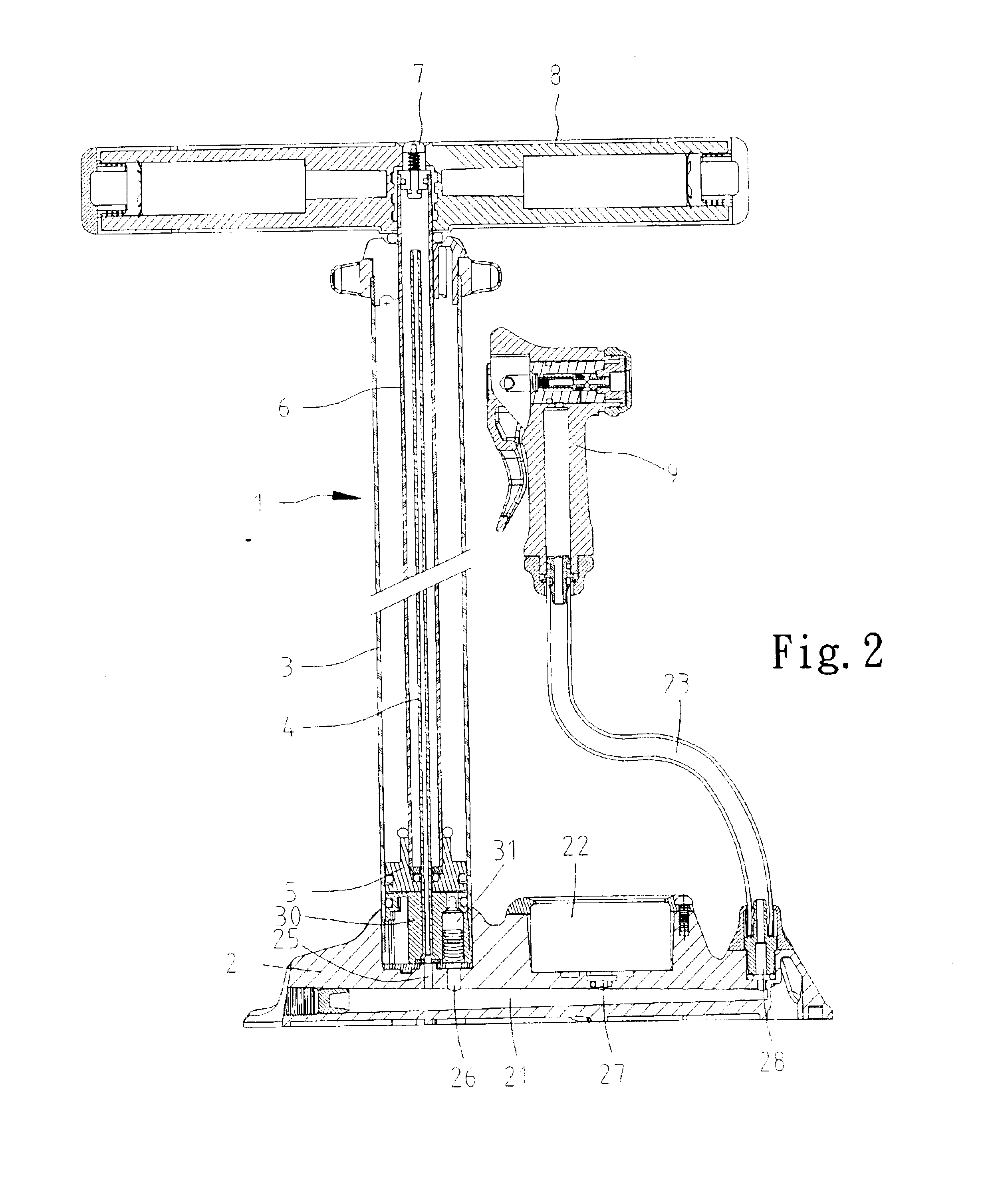
Referring to FIGS. 1 and 2, according to the preferred embodiment of the present invention, a pump 1 capable of releasing excessive air is shown to include a hollow base 2, a cylinder 3 installed on and communicated with the hollow base 2, a piston 5 movably received in the cylinder 3, a piston tube 6 including a lower end connected with the piston 5 and an upper end located beyond the cylinder 3, a tube 4 including a lower end communicated with the hollow base 2 and an upper end inserted into the piston tube 6 through a channel (not numbered) defined in the piston 5, a release valve 7 mounted on the upper end of the piston tube 6 and a handle 8 mounted on the upper end of the piston tube 6. The valve 7 is installed on the handle 8 so that it can be touched conveniently and operated easily by a user who is using the pump 1.

The base 2 includes two treads 24 on which the user can set his or her feet in order to hold the pump 1 still. The base 2 defines a trunk channel 21 and branch ch...


PUM


Abstract

A pump capable of releasing excessive air is shown to include a hollow base, a cylinder installed on and communicated with the hollow base, a piston movably received in the cylinder, a piston tube including a lower end connected with the piston and an upper end located beyond the cylinder, a tube including a lower end communicated with the hollow base and an upper end inserted into the piston tube through a channel defined in the piston, a release valve mounted on the upper end of the piston tube and a handle mounted on the upper end of the piston tube. The valve is installed on the handle so that it can be touched conveniently and operated easily by a user who is using the pump.

Description

BACKGROUND OF INVENTION1. Field of InventionThe present invention relates to a pump that is capable of releasing excessive air.2. Related Prior ArtTaiwanese Patent Publication No. 446070 teaches an upright pump including internal and external cylinders. This conventional pump includes a base 10, an internal cylinder 20 mounted on the base 10, a piston 43 movably received in the internal cylinder 20, a rod 41 connected with the piston 43, an external cylinder 50 mounted on the internal cylinder 20, a pressure gauge assembly 70 mounted on the external cylinder 50 and a nozzle 90 in communication with the pressure gauge assembly 70 through a pipe 80. The internal cylinder 20 defines a space 22 and an aperture 25 at a lower end in communication with the space 22. A space 52 is confined between the internal cylinder 20 and the external cylinder 50. The space 22 is in communication with the space 52 through the aperture 25. The external cylinder 50 defines an aperture 53 near an upper end...

Claims


Application Information

Patent Timeline
Patent Type & Authority Patents(United States)
IPC IPC(8): F04B33/00
CPCF04B33/005Y10T137/3677
Inventor WU, SCOTT
Owner SPECIALIZED BICYCLE COMPONENTS INC
Learn More