Stage apparatus and camera shake correction apparatus

a technology of camera shake and stage apparatus, which is applied in the direction of color television details, television system details, television systems, etc., can solve the problems of affecting the positioning of stage plates, difficult to drive (move) stage plates in the x-axis direction with a large driving force, and inability to slim down the thickness of camera shake correction apparatuses

Active Publication Date: 2013-08-01
RICOH IMAGING COMPANY
View PDF6 Cites 19 Cited by
  • Summary
  • Abstract
  • Description
  • Claims
  • Application Information

AI Technical Summary

Benefits of technology

[0021]The present invention provides a stage apparatus and a camera shake correcti

Problems solved by technology

However, since the control circuit board is positioned at the rear of the rear yokes, the thickness of the camera shake correction apparatus cannot be slimmed down.
According to the second example of the related art (Japanese unexamined patent publication No. 2011-81417), since there is only one X-direction drive coil, it is difficult to drive (move) the stage plate in the X-axis direction with a large driving force.
However, this solution (structure) still has the following problems.
However, due to increasing demand for miniaturized and light-weight camera body, the size of stage plate has become smaller (miniaturized), thereby causing unwanted restrictions on the positioning of the image sensor, the pair of X-direction drive coils and the pair of Y-direction drive co

Method used


Image

  • Stage apparatus and camera shake correction apparatus
  • Stage apparatus and camera shake correction apparatus
  • Stage apparatus and camera shake correction apparatus

Examples


first embodiment

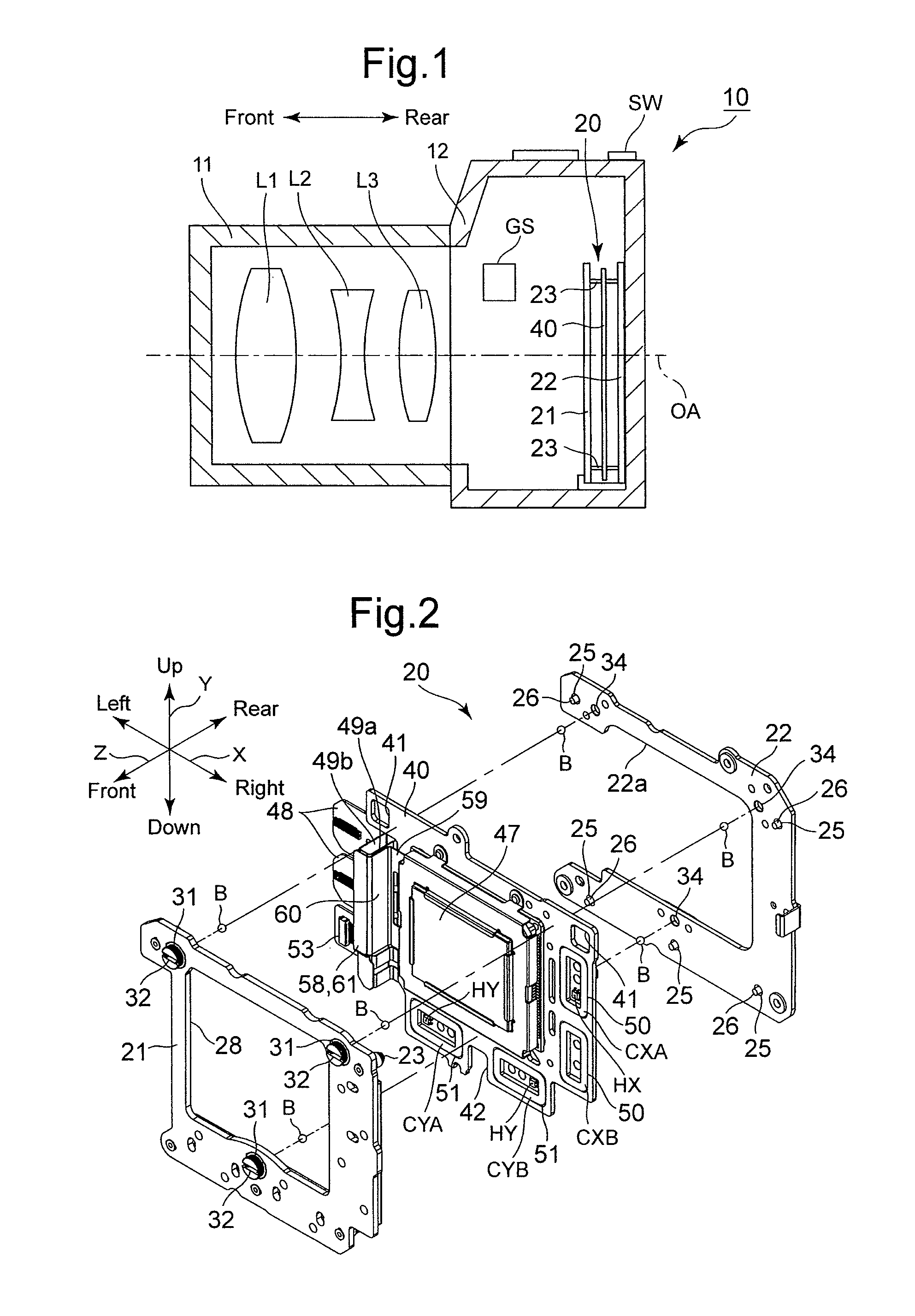
[0052]the present invention will be discussed in detail hereinafter with reference to FIGS. 1 through 9B. In the following description, the horizontal direction, the vertical direction and the forward / rearward direction of the digital camera 10 are referred to as an X-direction, a Y-direction and a Z-direction, respectively.

[0053]Firstly, the basic structures of the digital camera 10 and the camera shake correction apparatus 20 will be discussed hereinbelow.

[0054]As shown in FIG. 1, a lens barrel 11 of the digital camera 10 is provided therein with a photographing optical system including a plurality of lens groups L1, L2 and L3, and the camera shake correction apparatus 20 is provided in a camera body 12, to which the lens barrel is detachably attached, behind the rearmost lens group L3.

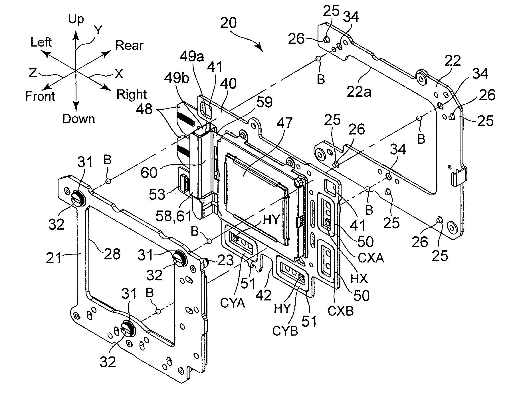
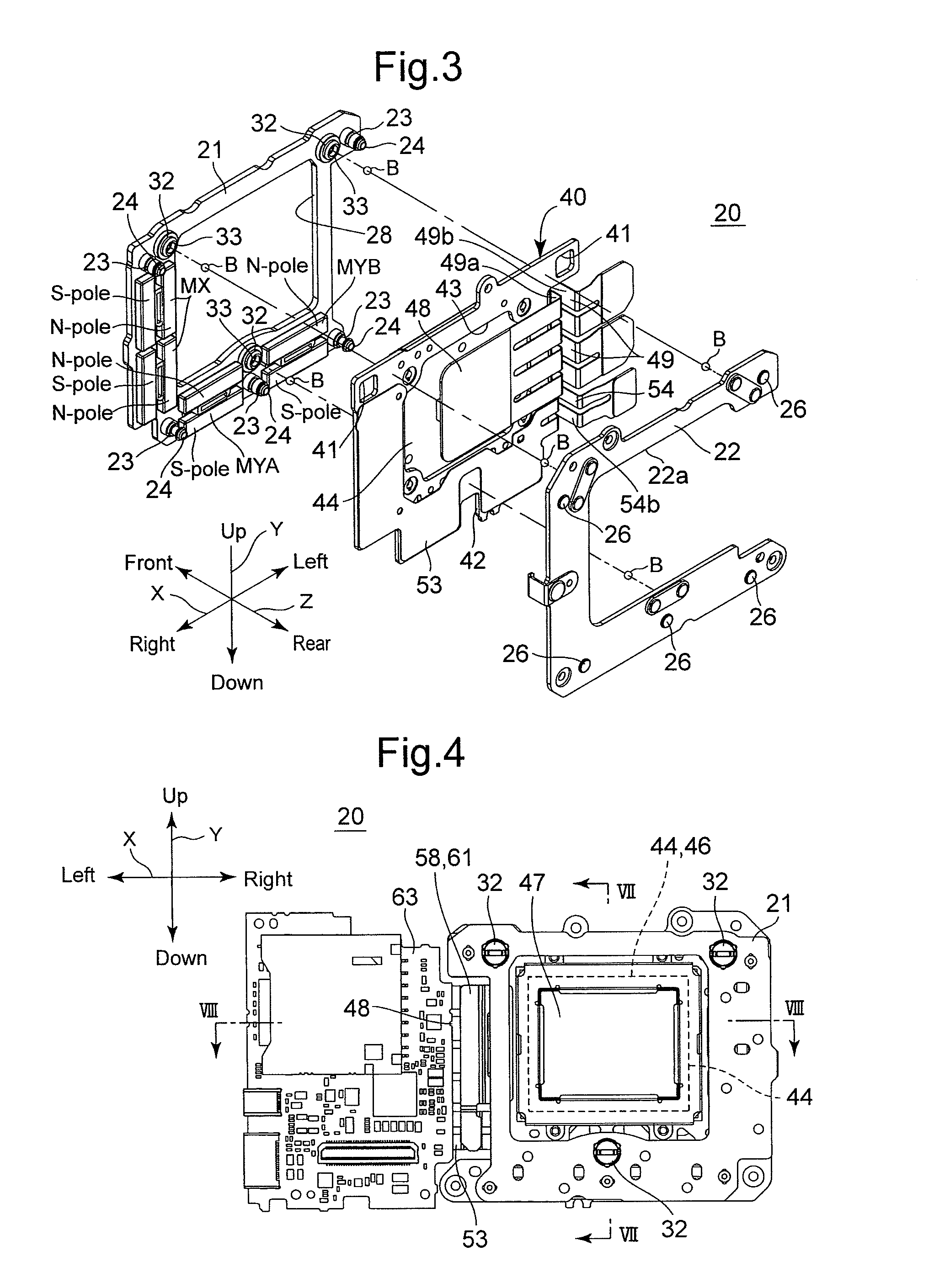
[0055]As shown in FIGS. 2 through 9B, the camera shake correction apparatus 20 is provided with a front yoke 21 and a rear yoke (stationary support plate) 22, respectively, each having a flat-plate ...

first modified embodiment

[0090]FIG. 10 shows the present invention, in which the distance in a direction parallel to the Y-direction edges 44Y from the reference straight line SLX to the center of driving force of the lower X-direction drive coil CXB is longer than the distance in the direction parallel to the Y-direction edges 44Y from the reference straight line

[0091]SLX to the upper X-direction drive coil CXA. Furthermore, according to the first modified embodiment, the lower X-direction drive coil CXB is positioned on the left side of the image sensor 44 and fixed to the stage plate 40, and as in the embodiment shown in FIG. 9B, the electric resistor 56 is provided in the electric circuit formed on the coil energization FPC board 53 and the control circuit board 63. The first modified embodiment of the present invention can also exhibit the same function and effect as those of the above illustrated embodiment.

second modified embodiment

[0092]FIG. 11 shows a second modified embodiment of the present invention, in which the lower X-direction drive coil CXB is positioned on the left side of the image sensor 44, while the upper X-direction drive coil CXA is positioned on the right side of the image sensor 44. In addition, the upper portion of the lower (left-side) X-direction drive coil CXB and the lower portion of the upper (right-side) X-direction drive coils CXA partially coincide with each other in the direction parallel to the Y-direction edges 44Y, relative to the reference straight line SLX. The distance in a direction parallel to the Y-direction edges 44Y from the reference straight line SLX to the center of driving force of the lower (right-side) X-direction drive coil CXB is longer than the distance in the direction parallel to the Y-direction edges 44Y from the reference straight line SLX to the upper (left-side) X-direction drive coil CXA, and as in the embodiment shown FIG. 9B, the electric resistor 56 is...


PUM


Abstract

A stage apparatus includes a stationary support plate, magnetic force generators immovable relative to the stationary support plate, a stage member, an image sensor fixed to the stage member, a control circuit board connected to a side of the stage member, and coils which produce a driving force upon a supply of electric current thereto, the coils being fixed to the stage member at an opposite side of the center of the stage member with respect to the control circuit board, and a FPC board between the stationary support plate and the stage member. The stationary support plate is recessed, from a lateral edge of the stationary support plate at which the control circuit board is provided, in a direction toward the coils and includes an FPC board escape recess, in which said FPC board is partially positioned.

Description

BACKGROUND OF THE INVENTION[0001]1. Field of the Invention[0002]The present invention relates to a stage apparatus including a movable stage supported to be movable in a specific plane, and a camera shake (image shake) correction apparatus incorporating the stage apparatus.[0003]2. Description of the Related Art[0004]As a first example of a camera shake correction apparatus (image shake correction apparatus / image stabilizer) of the related art, a camera, in which object images are captured by an image sensor (image pickup device / electronic device), is provided with a rear yoke (stationary support plate), a front yoke, a stage plate and a plurality of magnets. The rear yoke is fixed to an inner surface of the camera body, and the front yoke is positioned immediately in front of the rear yoke. The stage plate is positioned between the front yoke and the rear yoke, and is movable in a plane in a direction parallel to the both the front and rear yokes. The magnets are fixed to the rear ...

Claims


Application Information

Patent Timeline
IPC IPC(8): H04N5/232
CPCH04N5/23264H04N5/2328H04N5/23258H04N23/6812H04N23/685H04N23/682
Inventor YAZAWA, KAZUKI
Owner RICOH IMAGING COMPANY
Why Eureka
Try Eureka