Rotatable connector

a technology of rotating connectors and connectors, which is applied in the direction of flexible/turnable line connectors, coupling device connections, non-rotary current collectors, etc., can solve the problems of reducing the life of cables that are connected between electrical connectors and exterior electrical apparatuses, and affecting the service life of cables

Inactive Publication Date: 2004-11-09
CHENG UEI PRECISION IND CO LTD
View PDF6 Cites 31 Cited by
  • Summary
  • Abstract
  • Description
  • Claims
  • Application Information

AI Technical Summary

Problems solved by technology

As well-known, due to a movement of the exterior electrical apparatus, a cable that is connects between the electrical connector and the exterior electrical apparatus, especially a part approached to a cable end plug, would be tangled frequently.
This tangled cable not only influences beauty of the electrical equipment, but also results a bending stress and a stress concentration about the cable, further leads to the cable's life-span reduction, and even causes the cable damage or break.

Method used


Image

  • Rotatable connector
  • Rotatable connector
  • Rotatable connector

Examples


Embodiment Construction

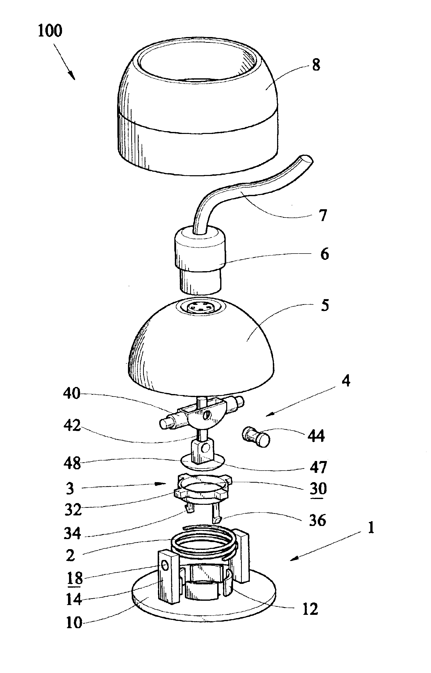
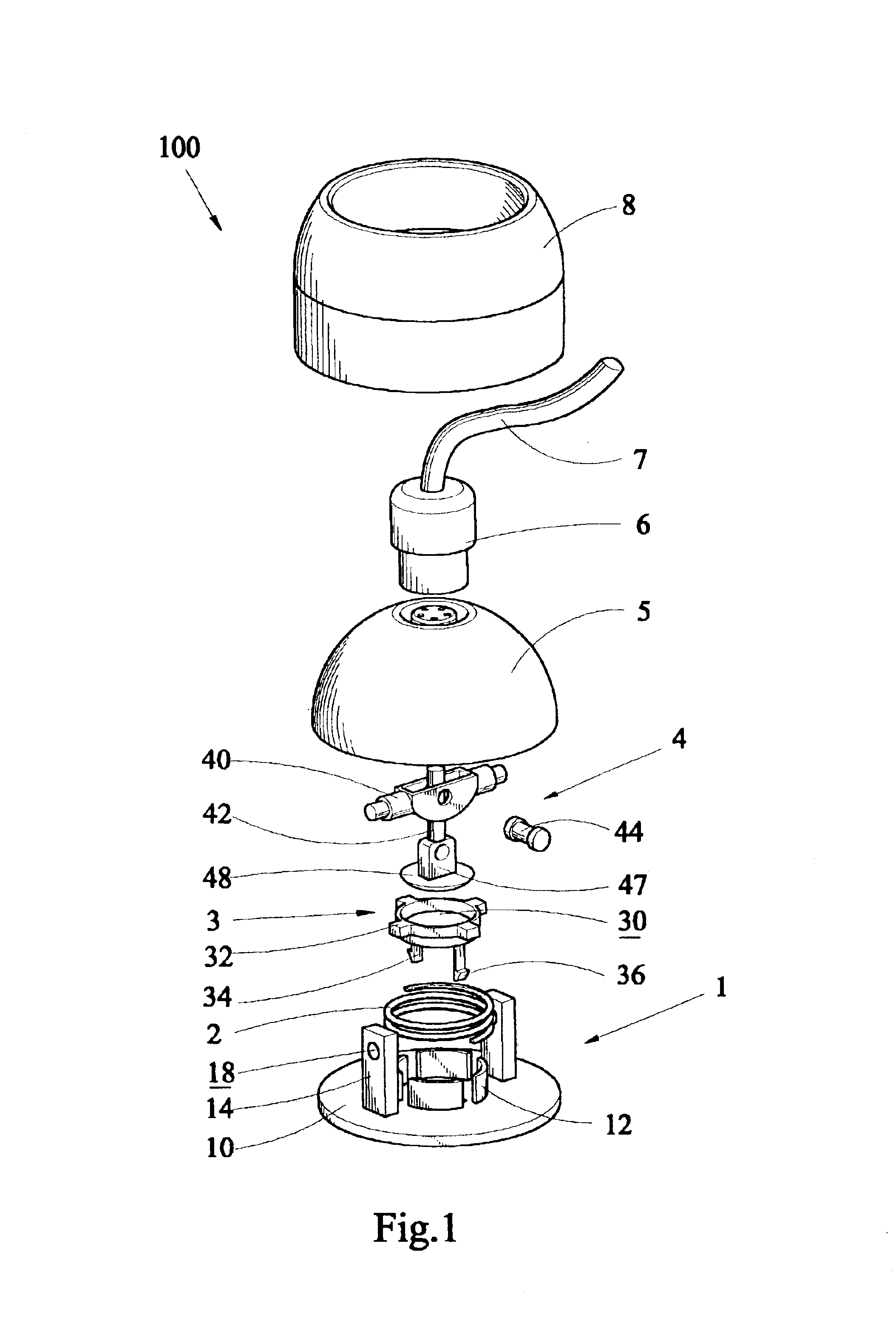
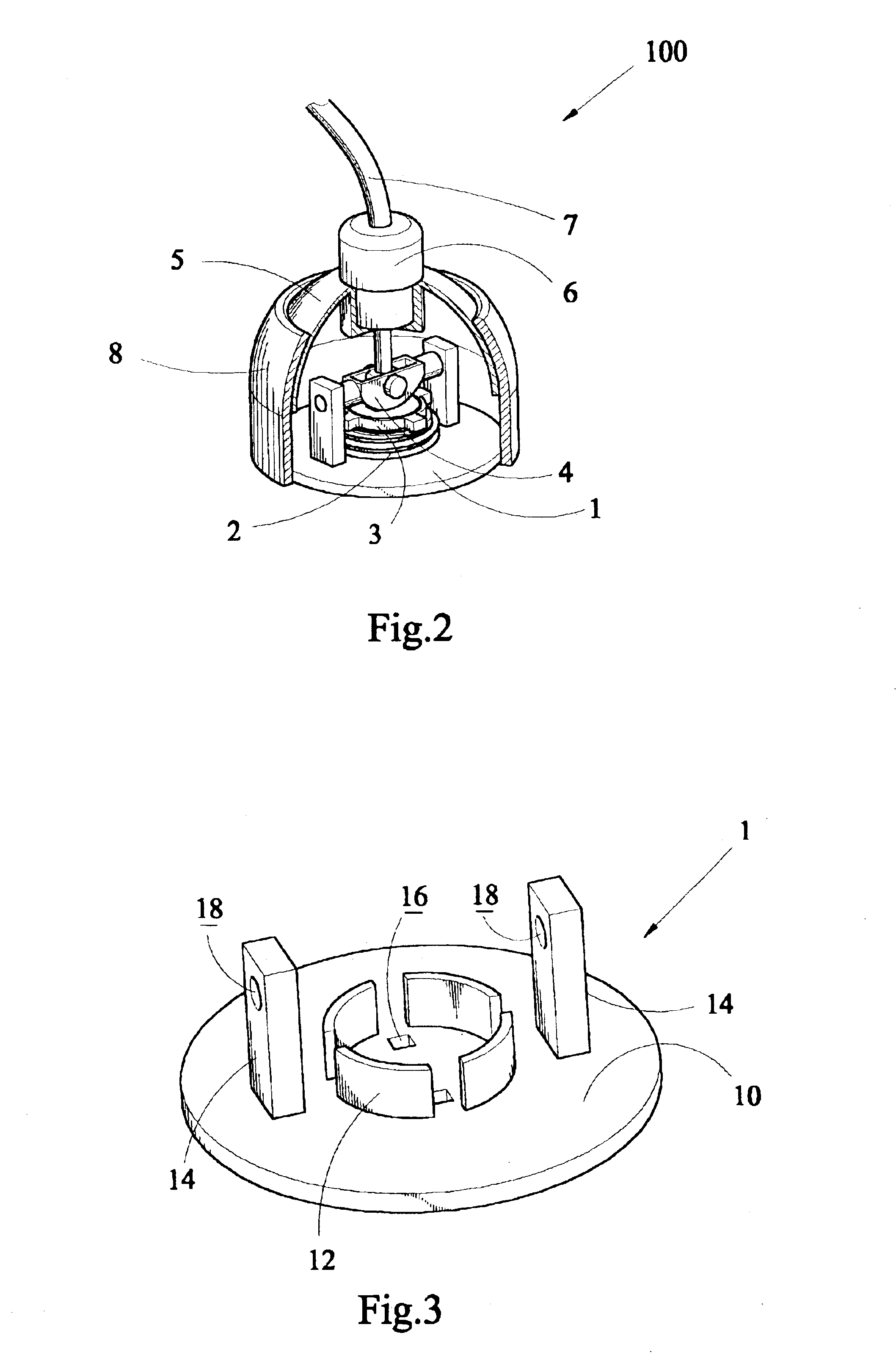
With reference to the FIG. 1, a rotatable connector, in accordance with the present invention, generally designed with reference numeral 100, comprises a pedestal 1, a spring 2, a holding plate 3, a universal coupling 4, a receptacle 5, a plug 6, a cable 7 and a housing 8.

As shown in FIG. 1 to FIG. 3, the pedestal 1 has a base plate 10 and several ledges 12 extending upwardly from a middle part of the base plate 10. The several ledges 12, as this embodiment illustrated, are four camber ledges which are disposed in a circumference position to form a cylinder, and defines four gaps therebetween. Two apertures 16 are formed inside a space surrounded by the several ledges 12 in the base plate 10. A pair of pillars 14 which are parallel each other are extended perpendicular to the base plate 10, standing opposite sides of the base plate 10 and outside the space surrounded by the several ledges 12. A couple holes 18 are formed on the pillars 14.

The spring 2 is arranged to encase the cylin...


PUM


Abstract

A rotatable connector comprises a pedestal, a spring, a holding plate, a universal coupling and a receptacle. The pedestal has a base plate, several ledges and a pair of pillars extending upwardly from the base plate. The pillars stand opposite sides of the base plate and outside the ledges. Each pillar has a hole therein. The spring is arranged to encase the ledges. A plurality of bulges is projected outwardly from an outer edge of the holding plate and pressed on the spring. The universal coupling has a first pivot, a second pivot and a shaft. The first and the second pivots are pivotally engaged by the shaft. Ends of the first pivot are pivotally inserted into the holes of the pillars. One end of second pivot engages with the holding plate, while the other end is fixed to the receptacle. The receptacle is electrically and mechanical connected to a cable end plug. Due to the universal coupling pivotally attaching to the pedestal, the rotatable connector can revolve following the plug's rotation, thereby avoiding the cable entangled.

Description

1. Field of the InventionThe present invention relates to a rotatable connector for electrical connection, and more particularly, to a rotatable connector having a universal coupling in order to avoid a cable entangled.2. The Related ArtElectrical connectors, as a common element that can be generally contacted by technical personnel, have an extensive application field. With respect to specific electrical equipments in which the electrical connector is used, it has an according request for connector structure corresponding to different purposes provided by the application of the electrical connector.At present, connector designers pay particular attention to achieve a variety of performance through making some certain improvements on the connector structure, i.e., simplifying constitution structure, realizing reliable electrical connection, or reducing the dimension and weight of the electrical connector.Although these variance designs as mentioned previously, can make a great progr...

Claims


Application Information

Patent Timeline
Patent Type & Authority Patents(United States)
IPC IPC(8): H01R35/00H01R39/00H01R35/04H01R39/64
CPCH01R39/643H01R35/04
Inventor LI, LI-HENGMU, MING-GANG
Owner CHENG UEI PRECISION IND CO LTD
Why Eureka
Try Eureka