Separable bottom end stop assembly for slide fastener

a technology of slide fastener and stop assembly, which is applied in the direction of slide fastener, snap fastener, press-button fastener, etc., can solve the problems of difficult engagement and separation operations, extremely difficult insertion operations for children and elderly people, etc., and achieves simple manner, easy closing, and simple operation.

Inactive Publication Date: 2004-12-07
YKK CORP
View PDF13 Cites 21 Cited by
  • Summary
  • Abstract
  • Description
  • Claims
  • Application Information

AI Technical Summary

Benefits of technology

The present invention obviates the aforementioned problems and has a principal object to provide a lateral-inserting type separable bottom end stop assembly of a slide fastener in which the engagement and separation operations are extremely simple and particularly, children and elderly people can perform the operation of closing of the left and right fastener stringers in a simple manner. That is to say, it is a principal object of the present invention to provide a separable bottom end stop assembly of a slide fastener in which the male member and the female member comprising the separable bottom end stop assembly can be engaged from both front and back directions, and by pulling together the male member and the female member and pressing both front and back surfaces thereof, the fastener stringers are closed easily due to cam mechanism, thereby causing initial movement of the slider, and in which separation of the left and right fastener stringers can be easily prevented, and further the separation and release of the left and right fastener stringers can be easily carried out.
According to the present invention, the slider which is attached to the fastener stringer is the one having a semiautomatic stopping device. When the engagement leg portion of the male member are engaged with the engagement hole of the female member in the left and right fastener stringers, and when the closing operation of the fastener chain is begun, the slider is in a release state. That is, when a pull of the slider is caused to fall to a shoulder side of the slider body, and when the pull is caused to stand on the slider body, a locking pawl of the slider is pulled up so as to maintain a state that the stop operation cannot be carried out. Consequently the pull of the slider is prevented from being an obstruction at the time of the engagement and release operation of the separable bottom end stop assembly, and the engaging mechanism is directly visible so that the engagement and release operation can be carried out quickly and easily.

Problems solved by technology

However, in this type of separable bottom end stop assembly in which the insert pin must be inserted in the box, the insertion operation is extremely difficult for children and elderly people.
Thus there is the problem that the engagement and separation operations are extremely difficult.

Method used


Image

  • Separable bottom end stop assembly for slide fastener
  • Separable bottom end stop assembly for slide fastener
  • Separable bottom end stop assembly for slide fastener

Examples


first embodiment

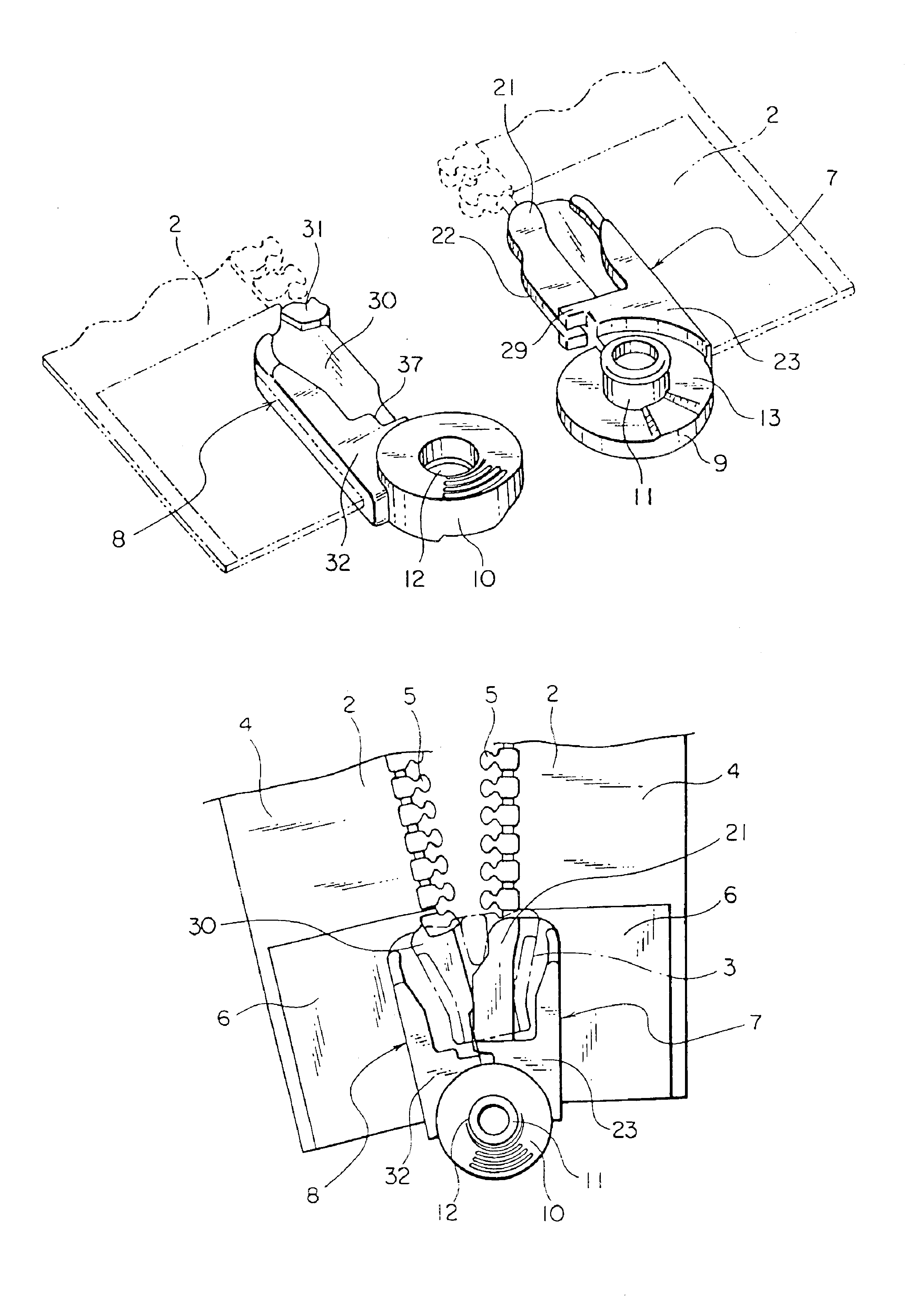
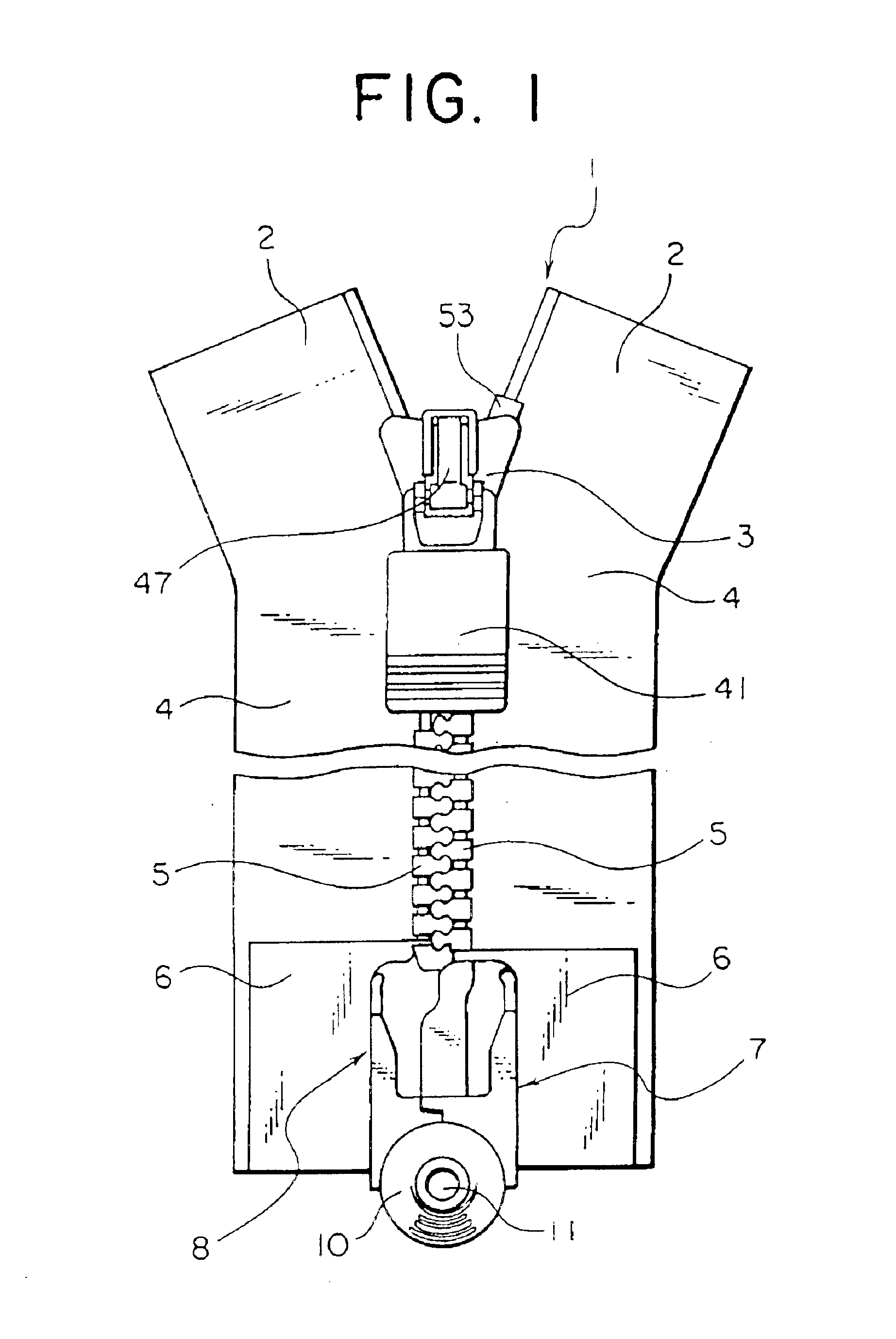
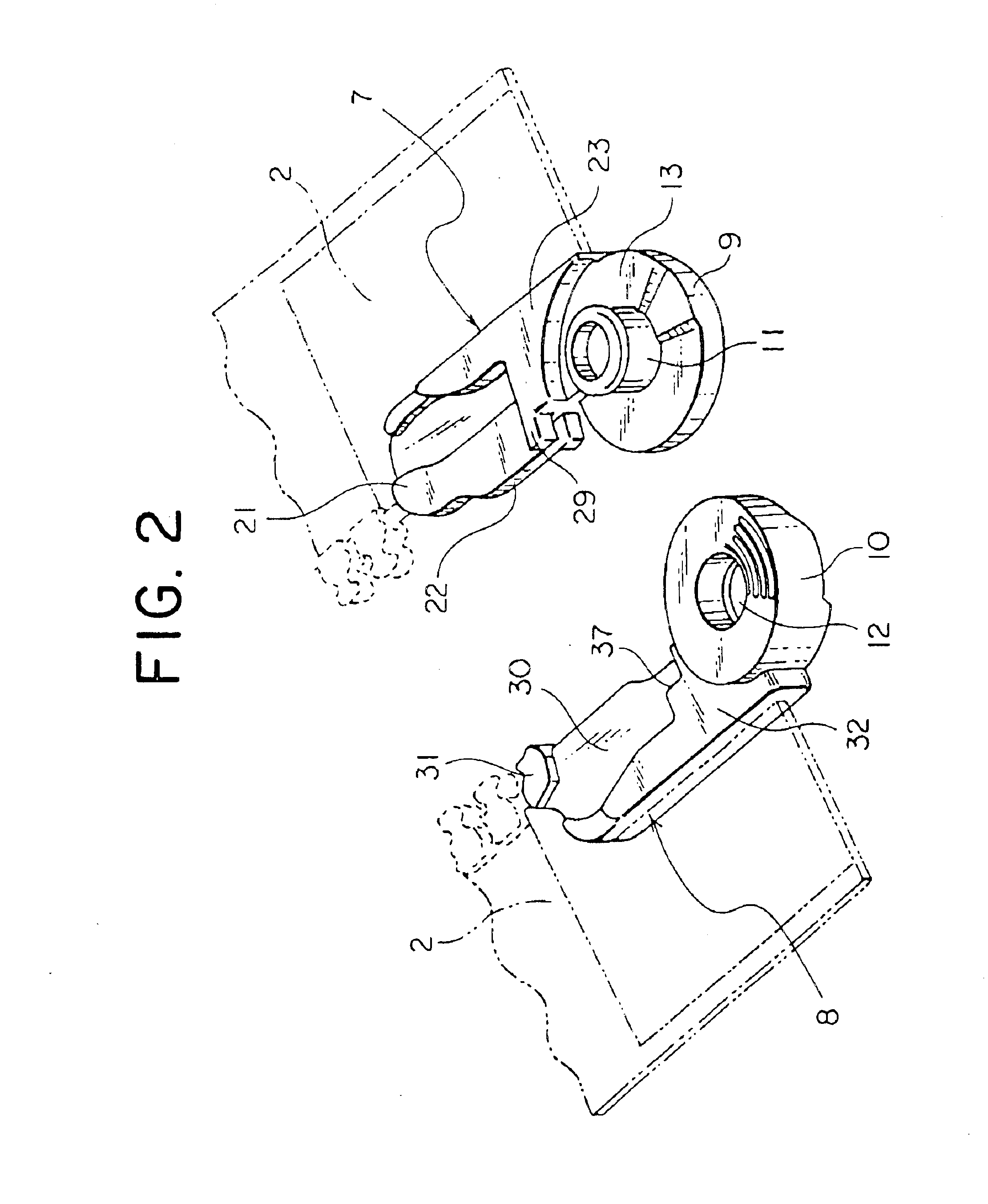
In the separable bottom end stop assembly shown in FIGS. 2 to 14, the male member 7 which is attached so as to be integral with the end portion of one of the fastener stringers 2, is as shown in FIGS. 6 and 7, provided with a circular slide plate 9 at a front terminal end thereof. In the center of this slide plate 9, an engagement leg portion 11, which is a pin, is provided so as to project from the front surface thereof. An enlarged engagement head portion 26 is provided at a front end of the engagement leg portion 11 so as to project sideways. Further, a concave portion 27 is provided on an inner side surface of the engagement head portion 26.

At the periphery of the base portion of the engagement leg portion 11 of the slide plate 9, a slide surface 13 having a step is formed. This slide surface 13 is circular, and has a vertical surface 15 at the portion along the side edge of the fastener tape 4, that is, from the holding portion 21 side toward the center of the engagement leg po...

second embodiment

The positional relationship of the joining of the slide surface 13 of the male member 7 and the slide surface 14 of the female member 8 will be described in the following. In order to engage the engagement head portion 26 of the engagement leg portion 11 and the engagement ridge 35 of the engagement hole 12, as shown in FIG. 20, the engagement is carried out at the time when the steep incline surface 19 of the slide surface 14 joins with the gentle incline surface 20 of the slide surface 13. In the state when the insert plate 30 is inserted between the guide flanges 44 of the slider 3, as shown in FIG. 19, the steep incline surface 18 and the gentle incline surface 20 of the slide surface 13 oppose and come in contact with the gentle incline surface 20 and the steep incline surface 19 of the slide surface 14 and there are small gaps between the upper step horizontal surface 16 of the slide surface 13 and the upper step horizontal surface 16 of the slide surface 14 and between the l...


PUM


Abstract

The separable bottom end stop assembly has male and female members engageable with and releasable from each other in a front-to-back direction thereof. A slide plate of the male member has an engagement leg portion projected therefrom, while a sliding plate of the female member has an engagement hole. Sliding surfaces are respectively formed at peripheries of the engagement leg portion and the engagement hole of the slide plates. Each of the slide surfaces is formed with steep incline surfaces and a gentle incline surface. With the cam mechanism, when the male member and the female member are pressed from both surfaces thereof, an insert plate disposed at one of the male member and the female member is automatically guided to an inside of the slider held by a holding portion disposed at the other of the male member and the female member, which simultaneously causes the slider to start moving.

Description

BACKGROUND OF INVENTION1. Field of the InventionThe present invention relates to separable bottom end stop assembly of a slide fastener. More particularly it relates to separable bottom end stop assembly of a lateral-inserting type slide fastener in which one of the separable bottom end stops attached to a lower end of a fastener stringer is a male member and the other is a female member, and after the male member and the female member are engaged from both surfaces of the fastener surface by a snapping system, the male member and the female member are caused to join up against each other from the transverse direction of the fastener, thereby fitting the fastener stringer inside the slider.2. Prior ArtIn the separable bottom end stop assembly of a slide fastener which has been used in the past, a box pin and a box are attached to an end portion of one of left and right fastener stringers and an insert pin is attached to the other fastener stringer. When the left and right fastener s...

Claims


Application Information

Patent Timeline
Patent Type & Authority Patents(United States)
IPC IPC(8): A44B19/24A44B19/38
CPCA44B19/388Y10T24/25Y10T24/2596Y10T24/2516Y10T24/2593Y10T24/2595Y10T24/2563A44B19/38
Inventor ICHIKAWA, NOBUHIROTAMURA, MIYAKO
Owner YKK CORP
Why Eureka
Try Eureka