Eureka AIR delivers breakthrough ideas for toughest innovation challenges, trusted by R&D personnel around the world.

Method and apparatus for estimating downlink beamforming weights in a communications system

a communication system and weight technology, applied in the field of communication systems, can solve the problems of increasing the amount of interference in the communication channel, making the downlink beamforming more difficult for fdd systems than tdd systems, and increasing the difficulty of tdd systems

Inactive Publication Date: 2005-01-04
INTEL CORP
View PDF9 Cites 46 Cited by
  • Summary
  • Abstract
  • Description
  • Claims
  • Application Information

AI Technical Summary

Problems solved by technology

This makes downlink beamforming more challenging for FDD systems than TDD systems since the uplink and downlink frequencies are the same in TDD systems.
As the number of separate sources or remote terminals utilizing the same frequency increases, the amount of interference in the communications channel also increases.

Method used


Image

  • Method and apparatus for estimating downlink beamforming weights in a communications system
  • Method and apparatus for estimating downlink beamforming weights in a communications system
  • Method and apparatus for estimating downlink beamforming weights in a communications system

Examples


Embodiment Construction

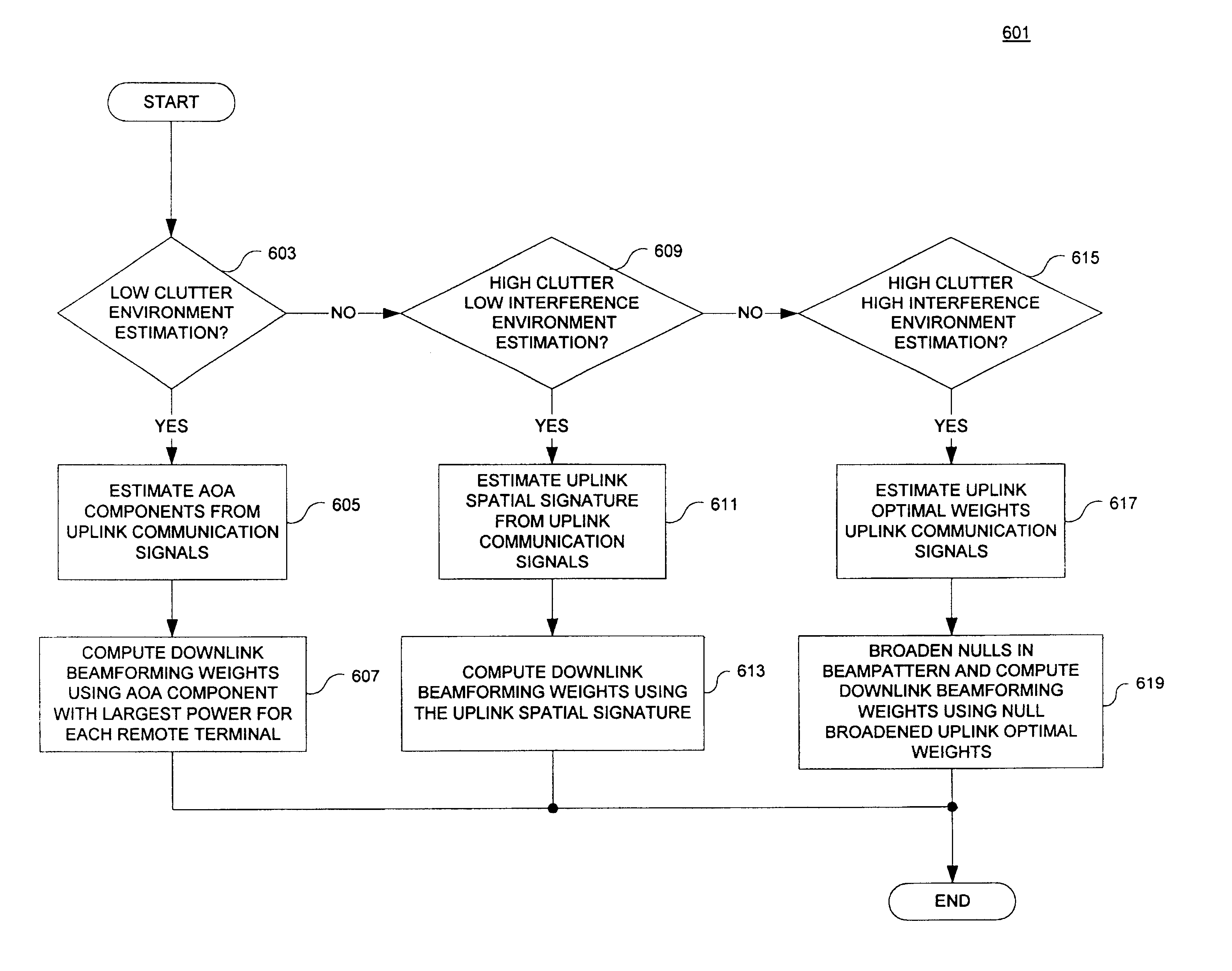
In one aspect of the present invention, methods and apparatuses for estimating downlink beamforming weights based on an operating condition or environment of a communications system are disclosed. In the following description, numerous specific details are set forth in order to provide a thorough understanding of the present invention. It will be apparent, however, to one having ordinary skill in the art that the specific detail need not be employed to practice the present invention. In other instances, well-known materials or methods have not been described in detail in order to avoid obscuring the present invention.

Reference throughout this specification to “one embodiment” or “an embodiment” means that a particular feature, structure or characteristic described in connection with the embodiment is included in at least one embodiment of the present invention. Thus, appearances of the phrases “in one embodiment” or “in an embodiment” in various places throughout this specification ...


PUM


Abstract

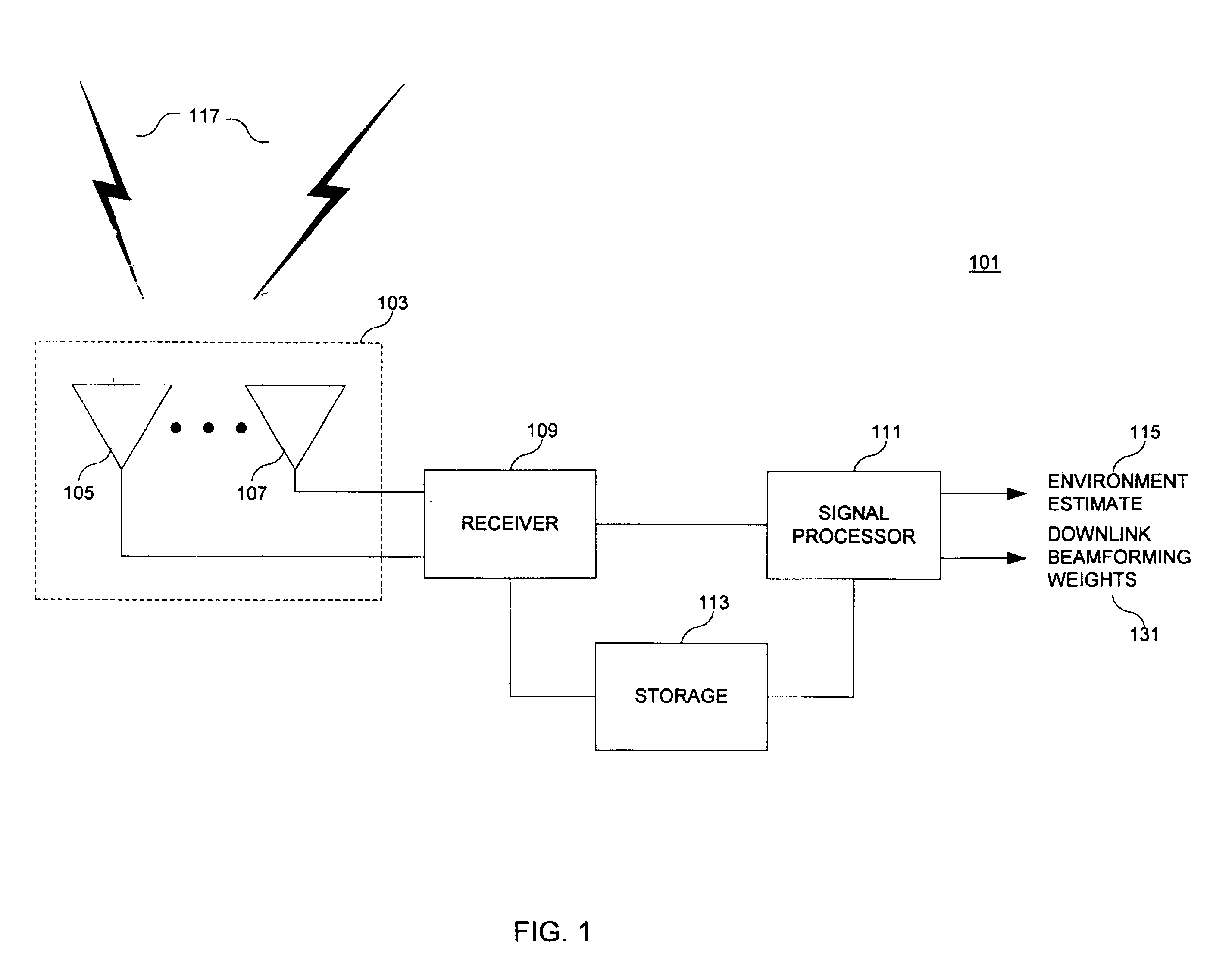
A downlink beamforming apparatus and method. In one embodiment, a method in accordance with the teachings of the present invention includes receiving uplink communication signals from a plurality of antenna array elements, selecting an operating condition of an environment and estimating downlink beamforming weights used in downlink communication signals in response to the selected operation condition of the environment.

Description

BACKGROUND OF THE INVENTION1. Field of the InventionThe present invention relates generally to communications systems and, more specifically, the present invention relates to wireless communications systems employing antenna arrays.2. Background InformationAntenna arrays may be used in communications systems that transmit and / or receive radio frequency signals. Antenna arrays typically include a number of antennas that are spatially separated and may be employed in a number of different wireless applications including radio communications systems, cellular systems, television broadcasting, point to point systems, paging systems, medical applications or the like.The use of antenna arrays in such systems often provide antenna performance improvements over the use of a single element antenna. These antenna performance improvements may include for received signals improved signal to noise ratio and interference rejection. Antenna performance improvements for transmitted signals may incl...

Claims


Application Information

Patent Timeline
IPC IPC(8): H04B7/04H04B7/06
CPCH04B7/0619H04B7/0617H04B7/06
Inventor PETRUS, PAULCHEMALI, ANTOINEDEPIERRE, DAVIDYUN, LOUIS C.
Owner INTEL CORP
Why Eureka
Eureka Blog
Learn More