Beamforming Weight Generation Using Adaptive Trigonometric Waveform Interpolation Techniques

a trigonometric waveform and waveform technology, applied in the field of wireless communication devices and systems, can solve problems such as difficulty in applying beamforming techniques in such a system

Active Publication Date: 2011-02-24
CISCO TECH INC
View PDF19 Cites 8 Cited by
  • Summary
  • Abstract
  • Description
  • Claims
  • Application Information

AI Technical Summary

Problems solved by technology

Consequently, it is difficult to apply beamforming techniques in such a system due to the lack of accurate channel information in some frequency bands.
Estimating the channel information in other frequency bands using, for example, feedback techniques, is one solution but it involves adding overhead to the communication link in one direction.

Method used


Image

  • Beamforming Weight Generation Using Adaptive Trigonometric Waveform Interpolation Techniques
  • Beamforming Weight Generation Using Adaptive Trigonometric Waveform Interpolation Techniques
  • Beamforming Weight Generation Using Adaptive Trigonometric Waveform Interpolation Techniques

Examples


example embodiments

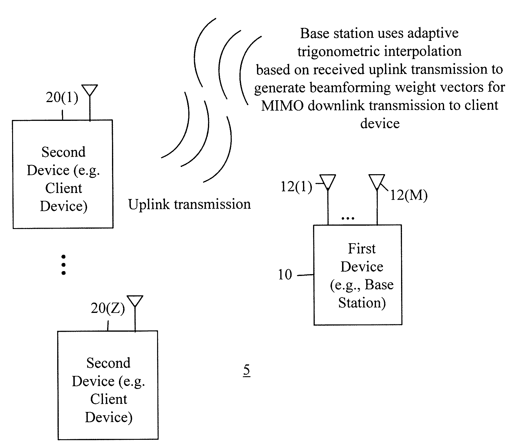
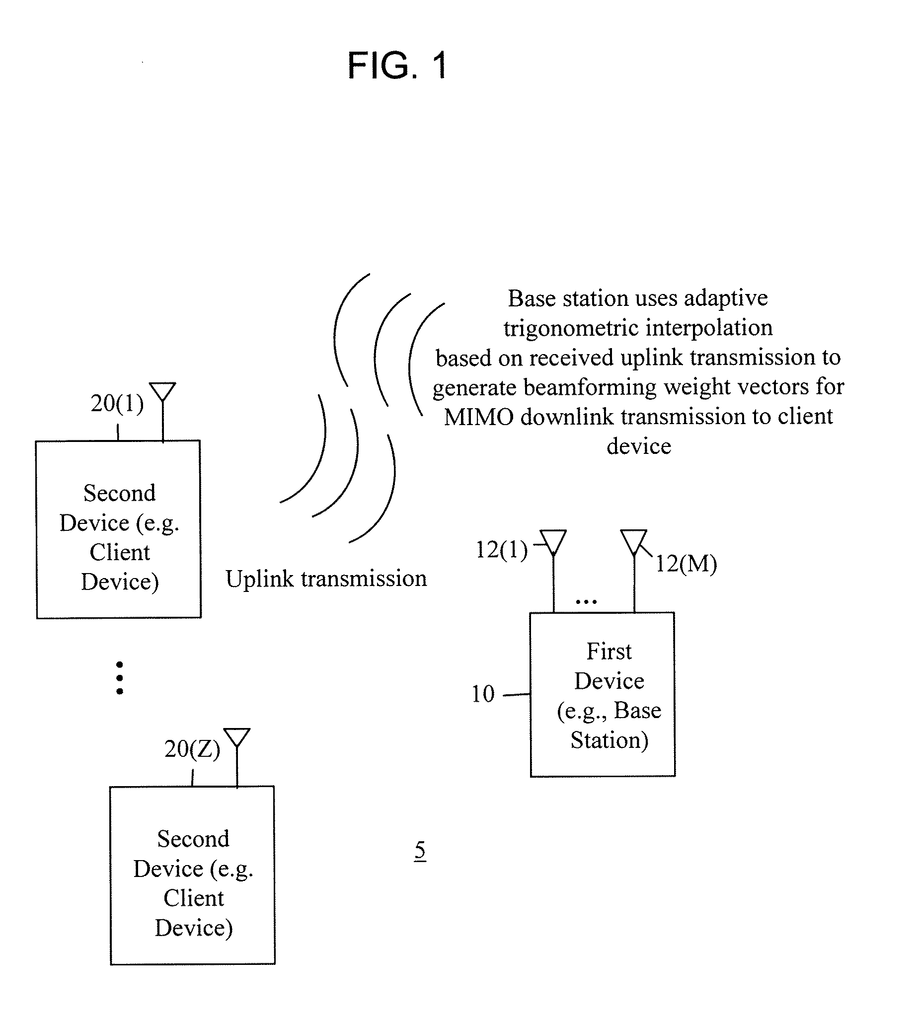
[0014]Referring first to FIG. 1, a wireless communication system is generally shown at reference numeral 5. The system 5 comprises a first wireless communication device 10, e.g., a base station that serves a plurality of second wireless communication devices (e.g., client devices) shown at 20(1)-20(Z).

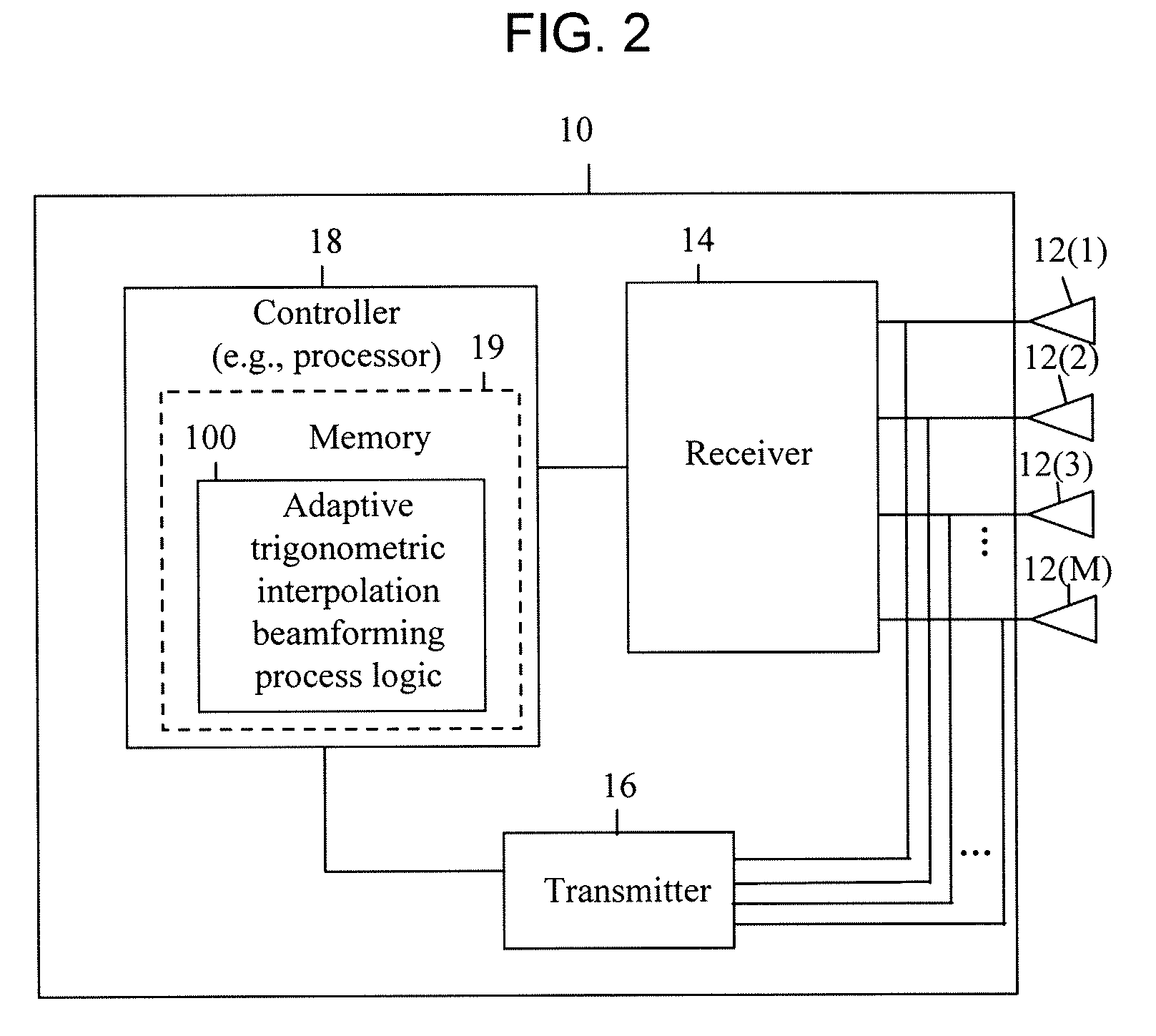
[0015]The base station 10 comprises M plurality of antennas 12(1)-12(M). The client devices 20(1)-20(Z) may comprise one or a plurality of antennas. The base station 10 may serve as a gateway for client devices to another network, i.e., the Internet.

[0016]The base station 10 is configured to receive uplink transmissions from a given client device, e.g., client device 20(1), and to use adaptive trigonometric interpolation based on the received uplink transmissions to generate downlink beamforming weight vectors for multiple-input multiple-output (MIMO) downlink transmissions to the client device 20(1). The base station 10 may perform this process with respect to communications with each...


PUM


Abstract

Techniques are provided herein to generate beamforming weight vectors for transmissions to be made from a first wireless communication device, e.g., a base station, to a second wireless communication device, e.g., a client device. The first device has a plurality of antennas and receives uplink transmissions from the second device, each uplink transmission comprising a group of frequency subcarriers. The first device computes channel information from the received uplink transmission and computes one or more trigonometric waveforms determined to approximate the channel information. One or more downlink beamforming weight vectors are computed at any given frequency subcarrier (thus in any frequency subband) by interpolation using the one or more trigonometric waveforms.

Description

TECHNICAL FIELD[0001]The present disclosure relates to wireless communication devices and systems and more particularly to techniques for generating beamforming weight vectors used for beamforming transmission from one device to another device.BACKGROUND[0002]In a wideband wireless communication system, the channel signatures in different frequency bands may be mutually uncorrelated. That is, the behavior of the wireless channel between two devices in one frequency band is different than that in another frequency band. Consequently, it is difficult to apply beamforming techniques in such a system due to the lack of accurate channel information in some frequency bands. Estimating the channel information in other frequency bands using, for example, feedback techniques, is one solution but it involves adding overhead to the communication link in one direction.[0003]In time division duplex (TDD) systems, the uplink channel coefficients describing the channel in the uplink direction (e.g...

Claims


Application Information

Patent Timeline
Patent Type & Authority Applications(United States)
IPC IPC(8): H04B1/06
CPCH04B7/0626
Inventor NA, YANXINJIN, HANG
Owner CISCO TECH INC
Why Eureka
Try Eureka