
Frequency transformation based transmit beamforming in a communication system

a technology of transmission beamforming and frequency transformation, which is applied in the direction of duplex signal operation, transmission path division, wireless commuication services, etc., can solve the problems of reducing the computational cost of fdd systems, requiring more attention to beamforming design, and affecting the quality of feedback

Inactive Publication Date: 2010-01-14
GOOGLE TECH HLDG LLC
View PDF5 Cites 17 Cited by
  • Summary
  • Abstract
  • Description
  • Claims
  • Application Information

AI Technical Summary

Benefits of technology

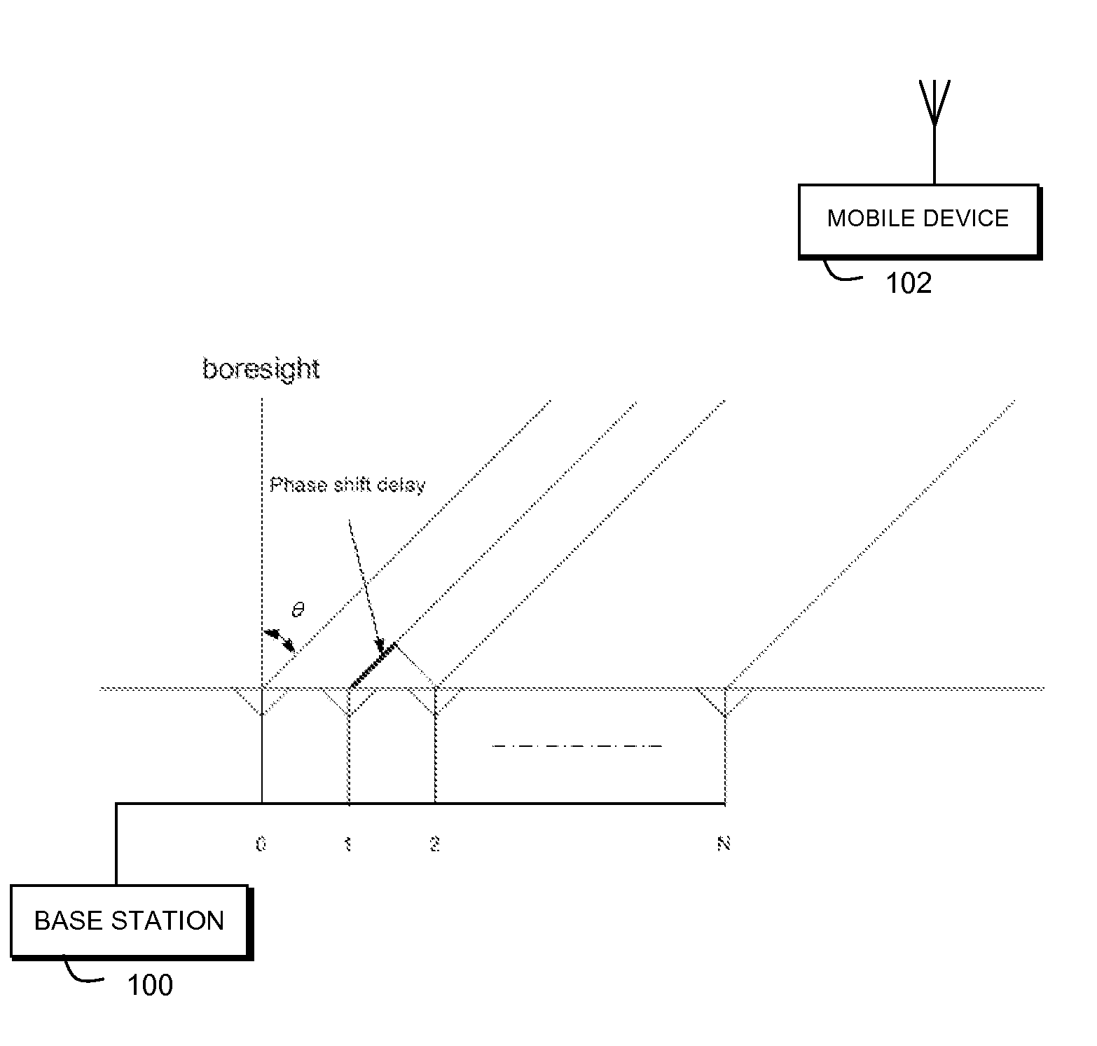
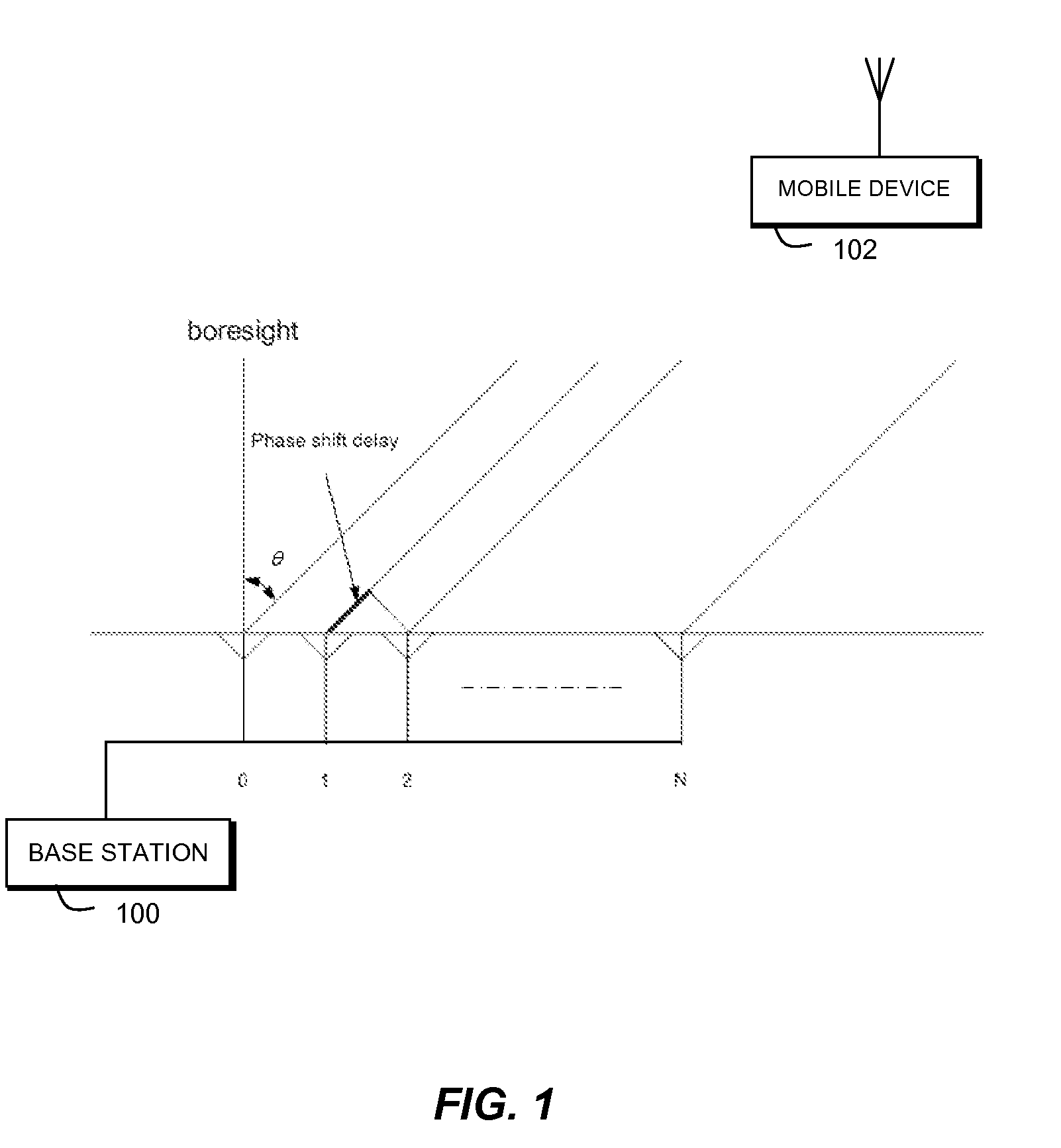
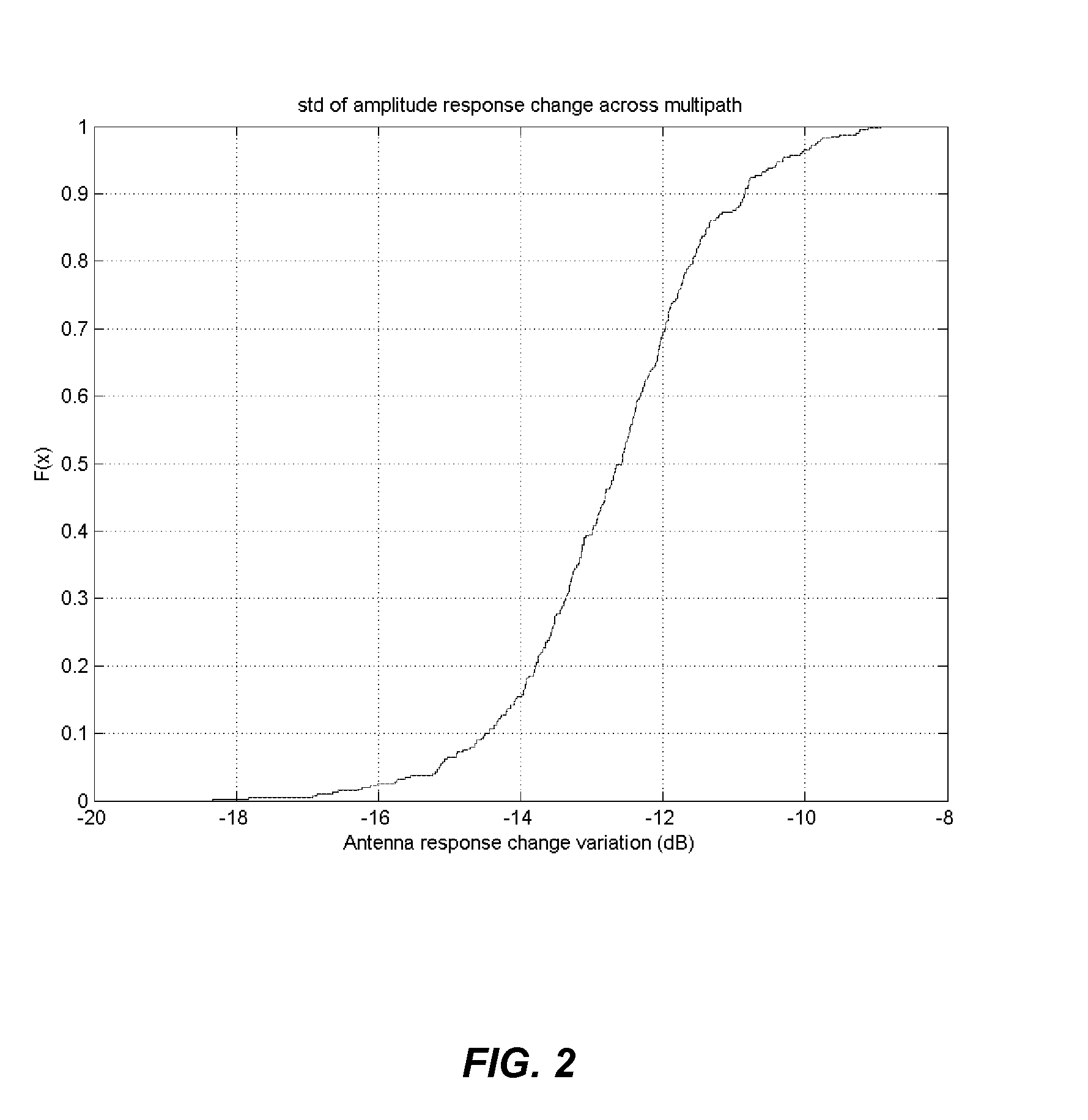
[0011]The present invention addresses transmit beamforming in Frequency Division Duplex (FDD) operation of a communication system based on the frequency transformation of the phase response. This technique can be used with eigen-beamforming and requires little processing. It should be noted that even though frequency translation has been studied in the art, those solutions are different from, and more complex than, the solution proposed by the present invention. In particular, the present invention provides a direct frequency transformation based beamforming and addresses the impact of unequal antenna response on the achievable beamforming gain. Simulation results (described below) show that the proposed eigen-beamforming is computational efficient and robust to antenna response variation.
[0012]The technique of the present invention described herein, provides a method for obtaining transmission weights in an FDD system without requiring feedback from the mobile. The loss in performance of the adaptive antenna due to uplink / downlink de-correlation in FDD is mitigated by a low complexity adjustment of the eigen-beamforming weight vector, which does not require feedback from the mobile.

Problems solved by technology

However, in Frequency Division Duplex (FDD) operation the downlink covariance matrix is different from the one obtained on the uplink, so the beamforming design in FDD systems requires more attention.
However, this scheme requires signaling overhead (which consumes uplink resources), and such feedback suffers from quantization error and bit errors in the course of signaling back the channel state information.
However, this approach requires angle of arrival (AoA) estimation, which is computationally intensive.
However the antenna response on the two frequency bands varies, and the calibration of the antenna response variation is extremely hard if not impossible to accomplish.
Therefore, the unequal antenna response on the uplink and downlink may have an adverse impact on the open-loop beamforming gain.

Method used


Image

  • Frequency transformation based transmit beamforming in a communication system
  • Frequency transformation based transmit beamforming in a communication system
  • Frequency transformation based transmit beamforming in a communication system

Examples


first embodiment

[0033]In a first embodiment, step 604 precedes step 606 and includes obtaining an uplink covariance matrix and taking the eigen-vector corresponding to the greatest eigen-value as the uplink beamforming weight. In this embodiment, in step 606 the uplink beamforming weight is transformed to a downlink beamforming weight by correcting for the frequency difference between the uplink and downlink by adjusting phase components. Specifically, the downlink beamforming weight is derived as

wd=[(-j2πd1ϕi21)]1×N

by frequency transformation.

second embodiment

[0034]In a second embodiment, this step 606 precedes step 604 and includes frequency translating sample uplink vectors prior to forming a sample covariance matrix in step 604, wherein the sample uplink eigen-vector corresponding to the greatest eigen-value is taken as the downlink beamforming weight. Specifically, the sample uplink beamforming weights are derived as the principal eigenvector of the matrix

Rd_est=∑kxk.xkH

where

xk=[vk,i(-j2πθk,i21)]1×Nandwherevk=⌊vk,i(-j2πθk,i)⌋1×N

represents the kth vector of received samples on the uplink, and wherein the sample uplink eigen-vector corresponding to the greatest eigen-value is taken as the downlink beamforming weight.

[0035]It should be noted that in either of the embodiments above, if there is a phase jump between neighboring phases, then a 360° complementary operation should be taken on the frequency transformation.

[0036]Advantageously, the present invention mitigates the loss in performance of the adaptive antenna due to uplink / downli...


PUM


Abstract

The present invention provides a system and method for transmit beamforming in a Frequency Division Duplex communication system. A first step (600) includes correcting for differences between transceiver receive and transmit responses within a base station. A next step (604) obtaining a beamforming weight of a phase antenna array on an uplink. A next step (606) transforming the uplink beamforming weight a downlink beamforming weight by applying a phase correction that is a function of wavelength at the uplink and downlink frequencies and distance between antenna elements.

Description

FIELD OF THE INVENTION[0001]The field of the invention relates to wireless communication systems, and in particular to, phased array transmit antennas in a communication system.BACKGROUND OF THE INVENTION[0002]With a phased array antenna installed at base station, beamforming can enable a base station to provide better coverage for mobile stations that are operating at the edge of the cell. To enable the base station to form a beam on the transmit side pointing in the right direction for a specific mobile station, the base station needs to know the spatial channel information. As is known in the art, a covariance matrix can be obtained by correlating the signal vector received at the phased array. In Time Division Duplex (TDD) operation, this covariance matrix observed on the uplink can be used for transmit beamforming given that the time delay between receiving and transmitting is within the coherence time of the time-variant channel. However, in Frequency Division Duplex (FDD) ope...

Claims


Application Information

Patent Timeline
Patent Type & Authority Applications(United States)
IPC IPC(8): H04L5/14H04M1/00
CPCH04B7/0617H04L5/0005H04B7/086
Inventor WHINNETT, NICK W.TONG, FEIVOOK, FREDERICK W.
Owner GOOGLE TECH HLDG LLC
Learn More