Apparatus for removing molten mass from confectionaries

a technology of molten mass and apparatus, which is applied in the field of apparatus for removing molten mass, can solve the problems of affecting the further processing of items, affecting the quality of confectionary, and the danger of a part of the edge breaking off, so as to achieve good quality, increase stability, and ensure the effect of removal

Active Publication Date: 2010-04-13
SOLLICH GMBH & CO KGAA
View PDF10 Cites 4 Cited by
  • Summary
  • Abstract
  • Description
  • Claims
  • Application Information

AI Technical Summary

Benefits of technology

[0013]The novel apparatus overcomes these drawbacks and operates in a reliable way even when processing short items and when using small gaps between the conveyor belts and a great working width, especially between 1,000 mm and 2,000 mm.
[0014]The novel apparatus includes a hollow shaft or a tube having an annular cross-section. Such a tube does not only have increased stability compared to a solid shaft. The hollow shaft also is less susceptible to fluttering, buckling and tensions building up. Due to the use of a hollow shaft and of a tube, respectively, there is the possibility to use the free cross-section of the hollow shaft to arrange a support which contacts the shaft from the inside without consuming much room. At the same time, there is the substantial advantage of the shaft being supported from the inside over the working width of the apparatus. In this way, elements protruding in an outward direction from the working width are omitted such that the surface of the tube can be moved very close to the deflecting locations of the two conveyor belts. This does not mean that known additional bearings may not be arranged outside of the working width, these bearings accommodating the hollow shaft. However, within the working width the dimensions of the hollow shaft and of the supporting element are coordinated in a way that the shaft may have a very small outer diameter which may be in a range of approximately 3 mm or even less. In this way, it is possible to arrange the ends of the first conveyor belt and the beginning of the following second conveyor belt very close to one another such that novel apparatus is especially suitable for processing small items, for example baby-sized filled chocolates. Important advantages of the hollow shaft being supported from the inside are certain recovery properties and a certain tendency to restore, respectively. It is still possible that a small crumb of a cookie, a splitter of a nut and the like which are broken off from the item reach the gap between the shaft and the stripper sheet metal which leads to the shaft partly leaving its predetermined location with respect to the stripper sheet metal. When supporting the shaft with magnetic forces as it is known in the prior art, these forces are reduced when the shaft leaves its predetermined position. The novel hollow shaft being supported from the inside results in these forces being increased when the shaft leaves its predetermined position. In other words, the hollow shaft is automatically returned to its predetermined location.
[0015]A supporting element may be arranged in the free cross-section of the driven hollow shaft, the supporting element at least extending over the working width of the free cross-section. Usually, the supporting element will also extend outside of the working width of the apparatus and through supports and bearings being located at that place and to extend through the motor. It is also possible to arrange a plurality of supporting elements in the free cross-section of the hollow shaft, the supporting elements being interconnected. This applies to the axial direction and / or to the radial direction. Usually, it is sufficient if the supporting element is arranged to be stationary, wherein a clearance required for the rotational movement of the hollow shaft with respect to the stationary supporting element is located between the supporting element and the hollow shaft. It is possible to take further measures for reducing friction between the supporting element and the hollow shaft.
[0017]The hollow shaft and the supporting element may be used with or without a heated stripper sheet metal. Usually, such a heated stripper sheet metal will be used to additionally support and guide the hollow shaft, on the one hand. On the other hand, the stripper sheet metal supplies the cleaning effect by removing the mass from the hollow shaft.
[0018]The hollow shaft and the associated supporting element may be arranged to be height adjustable. It is also possible to provide a possibility of an adjustment in the conveying plane to be capable of adjusting the respective distances with respect to the kind of the items in an optimal way.

Problems solved by technology

The rear frayed rim including the edges and tails does not only have a negative influence on the appearance, but it also negatively influences further processing of the items.
There is the danger of a part of these edges breaking off when the items are located on one or more following conveyor belts.
This leads to soiling of the conveyor belts during long operational times of the apparatus.
However, such edges may also have negative effects in packing machines being located downstream.

Method used


Image

  • Apparatus for removing molten mass from confectionaries
  • Apparatus for removing molten mass from confectionaries
  • Apparatus for removing molten mass from confectionaries

Examples


Embodiment Construction

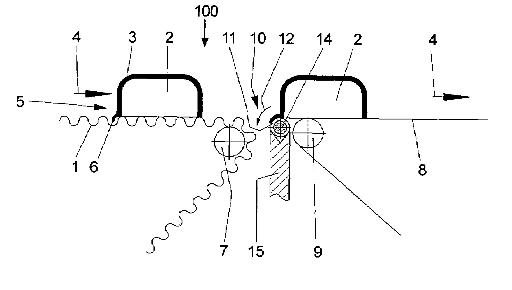
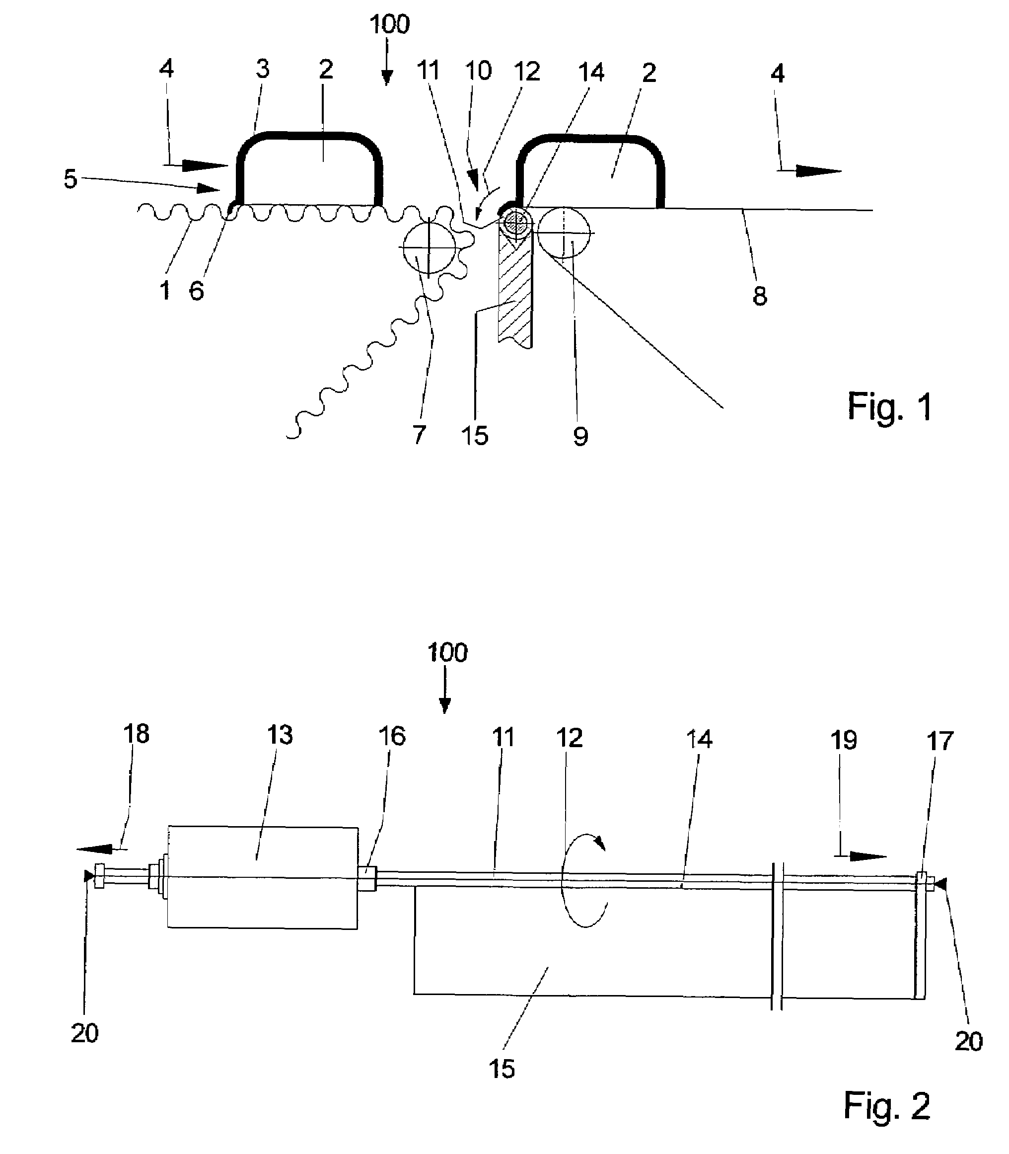
[0027]Referring now in greater detail to the drawings, FIG. 1 illustrates a first exemplary embodiment of a novel apparatus 100. The transition location between two adjacent conveyor belts is to be seen in FIG. 1. Items 2 are transported on a conveyor belt 1 which usually is designed as a grating belt. The grating belt is illustrated in an exaggerated way in FIG. 1. The items 2 are covered by a mass 3, or they are decorated with such a mass 3, and they are conveyed in the direction of arrow 4. Arrow 4 also indicates the direction of rotation of the conveyor belt 1. The item 2 illustrated in the left part of FIG. 1 which is transported on the conveyor belt 1 includes an edge 6 which more or less protrudes into the surface of the grating belt 1. Similar edges or ridges may be arranged about the circumference of the item 2, meaning in the front bottom portion and / or a lateral portion. Usually, these edges cause fewer problems than the edges located in the rear bottom portion 5. The con...


PUM


Abstract

An apparatus for removing molten mass, especially chocolate mass, from a rear bottom portion of items, especially confectionaries, includes a first and a second conveyor belt for transporting the items in a conveying direction perpendicular to the working width of the apparatus. The second conveyor belt is located adjacent to the fist conveyor belt and downstream of the first conveyor belt as seen in the conveying direction. A driven hollow shaft is located in a gap portion between the two conveyor belts, it extends over the working width, and it is supported from its inside and within the working width.

Description

CROSS REFERENCE TO RELATED APPLICATIONS[0001]This application claims priority to co-pending German Patent Application No. DE 10 2005 062 893.1 entitled “Vorrichtung zum Entfernen von Masse im Bodenbereich von Warenstücken”, filed Dec. 29, 2005.FIELD OF THE INVENTION[0002]The present invention generally relates to an apparatus for removing molten mass, especially chocolate mass, from the rear bottom portion of items, especially confectionaries.[0003]More particularly, the present invention relates to an apparatus including two adjacent conveyor belts, one being located downstream of the other one as seen in a conveying direction. A gap portion is located between the two conveyor belts in the conveying direction. The apparatus further includes a driven shaft being located in the region of the gap portion.[0004]When confectionary items such as serial bars, cookies, candy and the like, for example, are to be coated with a mass, the molten coating mass is supplied by and in a coating mac...

Claims


Application Information

Patent Timeline
Patent Type & Authority Patents(United States)
IPC IPC(8): A23L1/00
CPCA23G1/205A23G3/22A23G3/20A23G3/0252
Inventor BAUMER, VOLKER
Owner SOLLICH GMBH & CO KGAA
Why Eureka
Try Eureka