Continuous processing device

Active Publication Date: 2015-08-06
TSUKISHIMA KIKAI CO LTD
View PDF8 Cites 6 Cited by
  • Summary
  • Abstract
  • Description
  • Claims
  • Application Information

AI Technical Summary

Benefits of technology

The present invention enables a small processing device to achieve both a large amount of processing and stable contact processing.

Problems solved by technology

However, there is a limit beyond which the expectation for the uniform reactions cannot go.
Meanwhile batch processing cannot be applied with high efficiency where the components are fed into the contact processing reactor 1 and stirred afterward.
However, in the continuous production system, it is difficult to set conditions for contact processing (ex. control of the amount of fed components with respect to lapse of time) so that homogenous products cannot be always efficiently obtained.
However, in such micro reactor, there are problems such as a small processing amount, failure of continuous production due to blockage of the flow path, resulting in small number of practical examples on an industrial scale.

Method used


Image

  • Continuous processing device
  • Continuous processing device
  • Continuous processing device

Examples


example 1

Example of Nickel Manganese Cobalt Hydroxide

[0169]As the reactant A, 1.6 M liquid obtained such that nickel sulfate, manganese sulfate, and cobalt sulfate are mixed at a ratio of 1:1:1 was used. As the reactant B, 25% sodium hydroxide was used, and as the reactant C, 25% ammonia water was used. To advance predetermined reaction, it is common that solvent adjustment is performed to the reactant A by addition of ammonium sulfate, hydrogen peroxide, ethanol, glycerin, or the like and in this example, 0.1 M of ammonium sulfate was added.

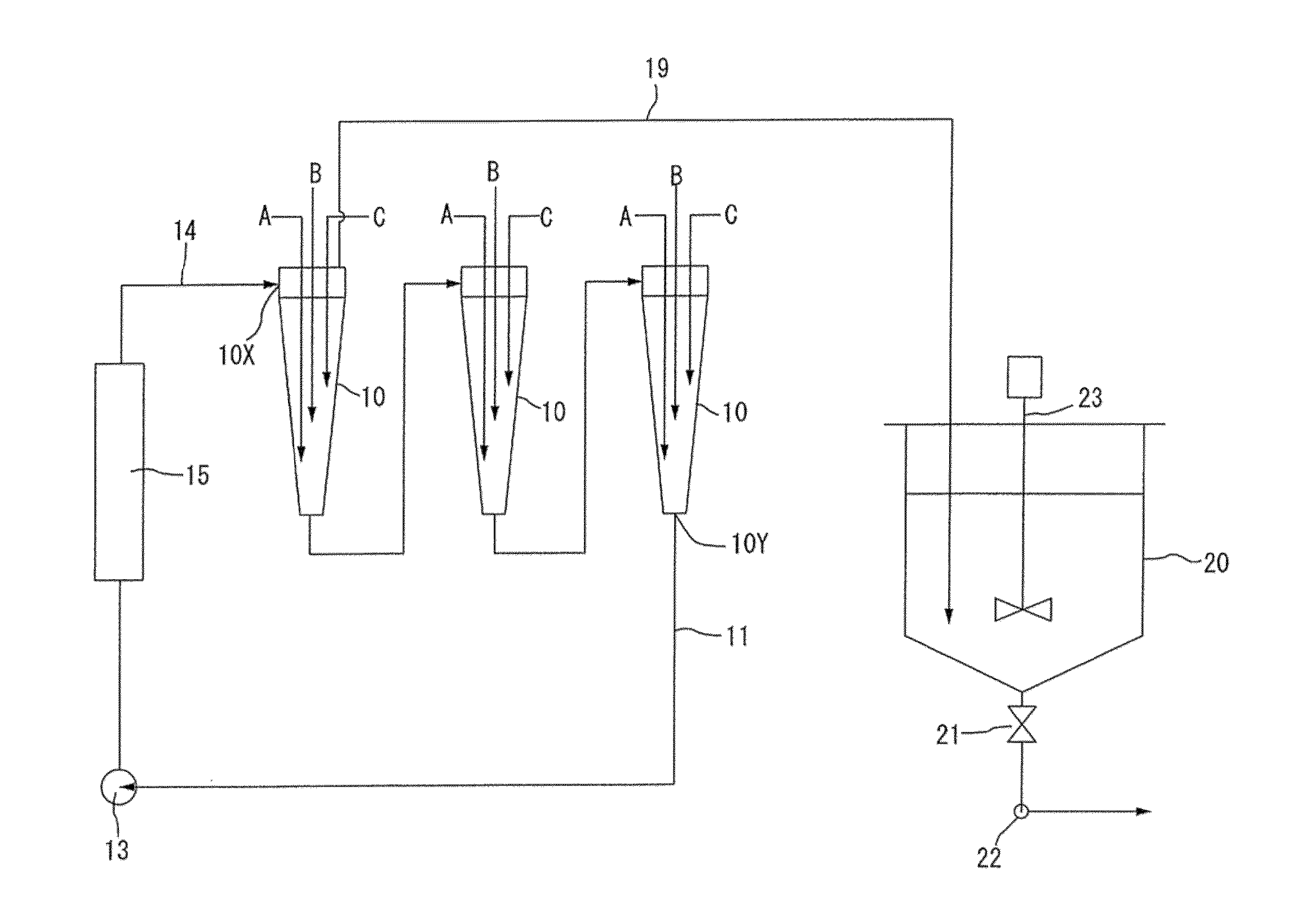
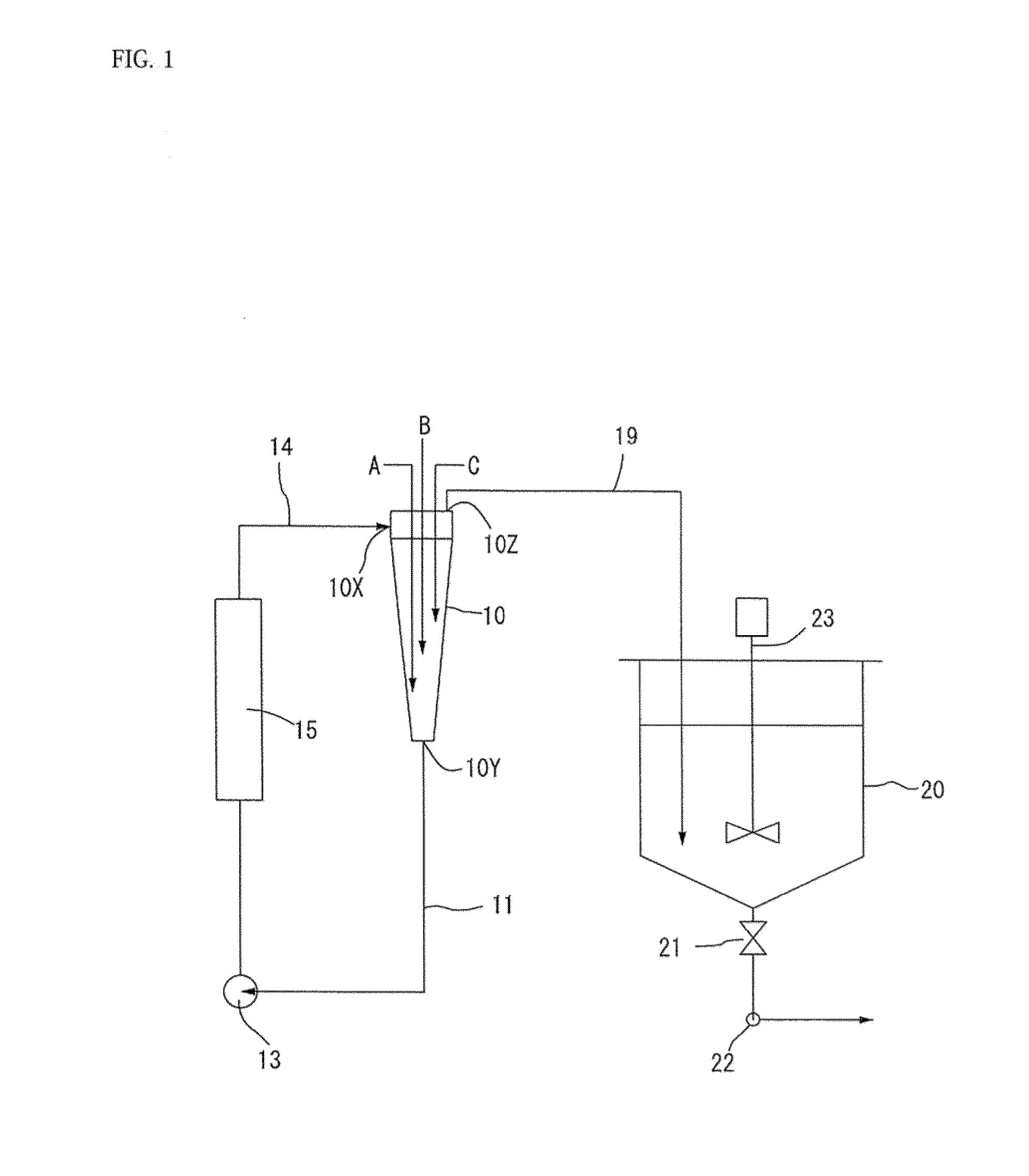
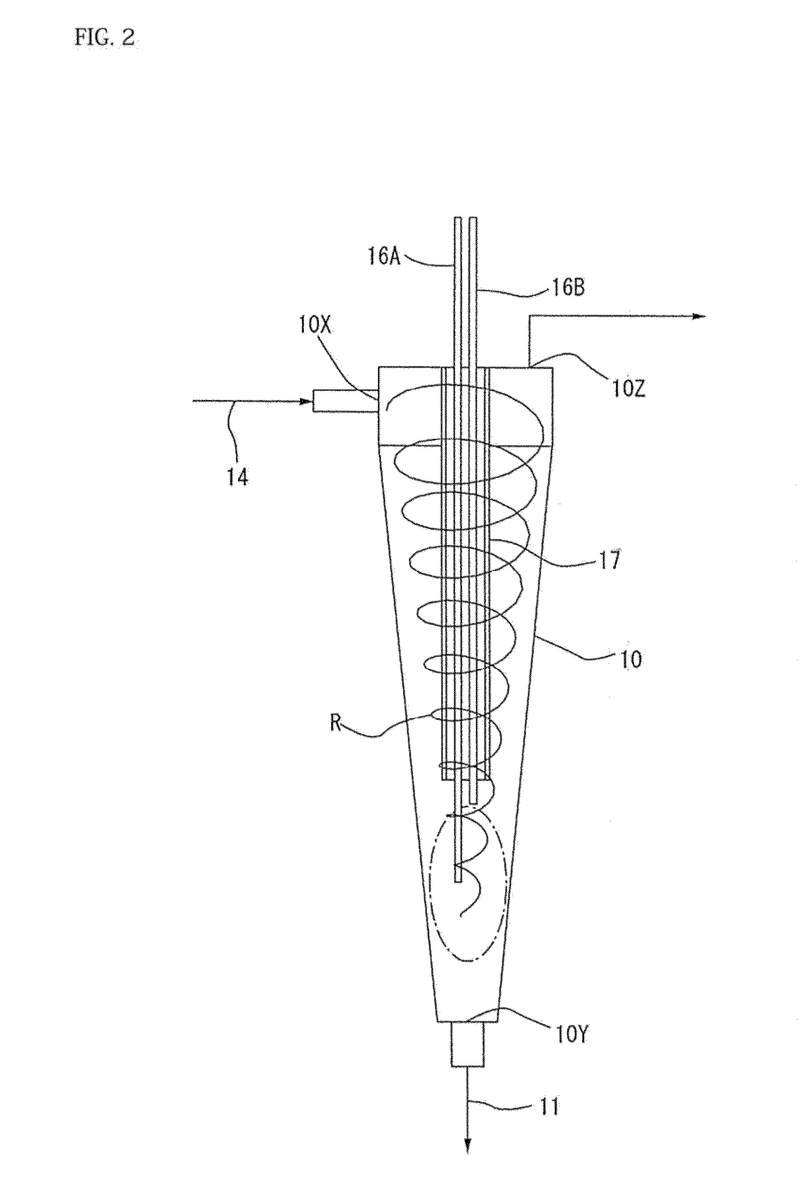
[0170]The reactant A, the reactant B and the reactant C were injected into the processing vessel 10 in the embodiment of FIGS. 1 to 4.

[0171]A start mother liquor prepared such that 40 g of ammonia water is added to 2 kg of ion exchange water was used.

[0172]The circulation pump was operated at 20 L / min, about 120 g / min of the reactant A, about 40 g / min of the reactant B, and about 3 g / min of the reactant C were injected. Further, 50 ml / min of an N2 gas wa...

example 2

Example of Manufacturing Emulsion Fuel

[0182]A liquid prepared with 1 L of water, 1 L of a light oil and an emulsifier, which was injected to have 3.4% of 1 L of water, were circulated in the present device at a flow rate of 10 L / min for one minute, then water, the light oil, and the emulsifier were added to the reaction unit at 200 mL / min, 250 mL / min, and 34 g / min, respectively, and were discharged by overflow.

[0183]An O / W type emulsion fuel was obtained, and kept the emulsified state after the lapse of one week.

[0184]When a static mixer was used in the reaction unit, oil-water separation occurred after the lapse of one day.


PUM

PropertyMeasurementUnit
Flow rateaaaaaaaaaa
Diameteraaaaaaaaaa
Lengthaaaaaaaaaa

Abstract

To provide a processing device which is small but which can exhibits a sufficient processing amount and a uniform contact processing property. In the processing vessel 10, a liquid flow is set to a spiral flow, and in a contact processing field, the injection liquid A, B are injected at a center-side position with respect to an inner surface of the processing vessel so as to perform contact processing.

Description

TECHNICAL FIELD[0001]The present invention relates to a continuous processing device that circulates a processed liquid, and especially relates to a continuous reaction device accompanying a reaction.BACKGROUND ART[0002]There are lots of operations of obtaining products or intermediate products through industrial processing, such as reactions including a liquid-liquid reaction, a gas-liquid reaction, and a catalyst reaction, as well as generation of particles by crystallization.[0003]Typical processing is illustrated in FIG. 23 in which component A, component B or component C are fed into a stirred contact processing reactor 1 and are stirred with a stirring blade 3 having a stirring motor 2 so as to facilitate the reactions of the components. Then, a product liquid is discharged through a discharge outlet 5 at appropriate timing and after that, crystallization particles are obtained by filtration, washing and drying for example. The reference numeral 4 is designated as a baffle 4.[...

Claims


Application Information

Patent Timeline
IPC IPC(8): B01J19/24B01J19/18
CPCB01J19/2405B01F5/10B01F5/0065B01F5/0071B01F7/18B01F13/1016B01J2219/2401B01F3/0865C01G53/006C01P2004/03B01J19/1862B01J19/24B01F3/0853B01F23/43B01F23/451B01F25/1041B01F25/103B01F25/50B01F27/90B01F33/811B01F33/813B01F35/92C01G53/00B01J19/242B01J19/2435
Inventor DOYA, YOGOTO, HIDENORI
Owner TSUKISHIMA KIKAI CO LTD
Why Eureka
Try Eureka