
Spray nozzle, in particular for a system for dispensing a pressurized fluid provided with a pushbutton, and dispensing system comprising such a nozzle

a technology of spray nozzle and pushbutton, which is applied in the direction of spray nozzle, liquid dispensing, single-unit apparatus, etc., can solve the problems of significant turbulence and flow turbulence, and achieve the effect of significant turbulen

Active Publication Date: 2020-07-21
SILGAN DISPENSING SYST LE TREPORT
View PDF28 Cites 0 Cited by
  • Summary
  • Abstract
  • Description
  • Claims
  • Application Information

AI Technical Summary

Benefits of technology

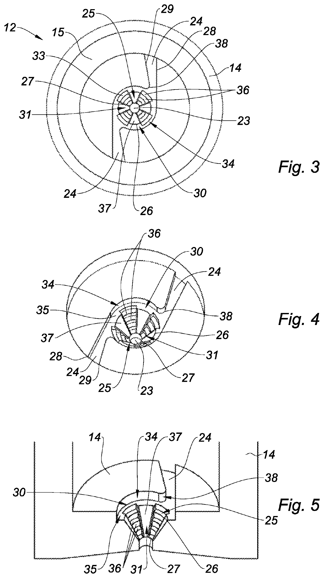
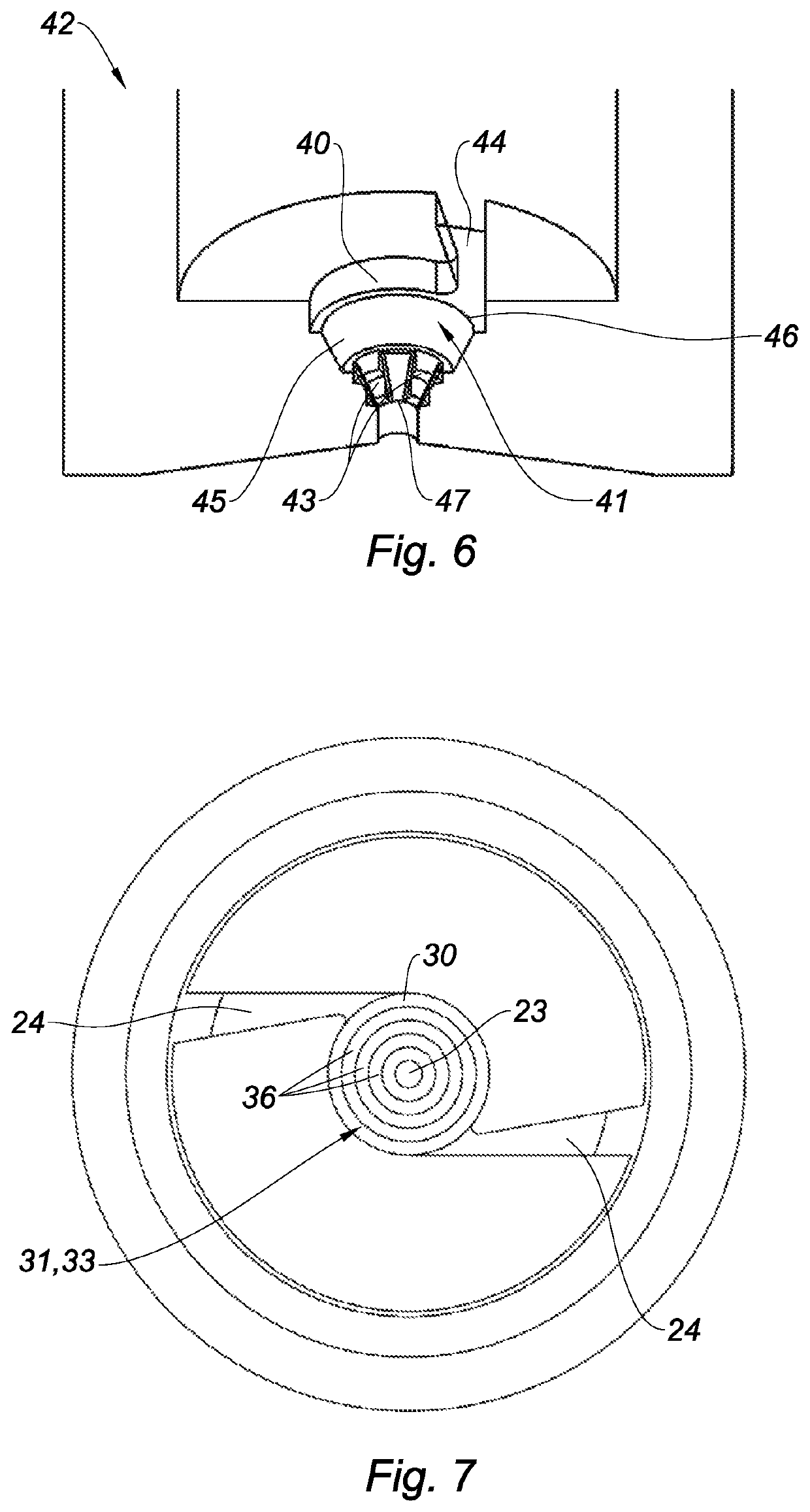
[0011]The stepped portions favor greater impaction of the pool on itself, and thus the formation of fine enough droplets. Indeed, when the fluid rotates in the form of a laminar pool on the surface of the conical part and approaches the outlet orifice, the pool jumps from one stage to the other between two levels, which causes the turbulence of the flow. One thus manages to create significant turbulence despite the viscosity of the product.

Problems solved by technology

Indeed, when the fluid rotates in the form of a laminar pool on the surface of the conical part and approaches the outlet orifice, the pool jumps from one stage to the other between two levels, which causes the turbulence of the flow.
One thus manages to create significant turbulence despite the viscosity of the product.

Method used


Image

  • Spray nozzle, in particular for a system for dispensing a pressurized fluid provided with a pushbutton, and dispensing system comprising such a nozzle
  • Spray nozzle, in particular for a system for dispensing a pressurized fluid provided with a pushbutton, and dispensing system comprising such a nozzle
  • Spray nozzle, in particular for a system for dispensing a pressurized fluid provided with a pushbutton, and dispensing system comprising such a nozzle

Examples


first embodiment

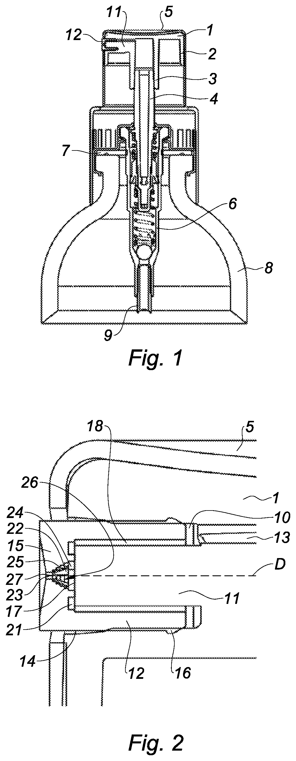
[0064]FIG. 1 shows a cosmetic product bottle comprising a system for dispensing a pressurized product according to a The dispensing system is provided with a pushbutton. The pushbutton comprises a body 1 having an annular skirt 2 that surrounds a well 3 for mounting the pushbutton on an intake tube 4 for the pressurized product. Furthermore, the pushbutton comprises an upper zone 5 allowing the user to exert pressure on said pushbutton using a finger so as to be able to move said pushbutton axially.

[0065]The dispensing system comprises a withdrawal device 6 equipped with an intake tube 4 for the pressurized product that is inserted tightly into the well 3. In a known manner, the dispensing system further comprises mounting means 7 for mounting on a bottle 8 containing the product and withdrawal means 9 for withdrawing the product from inside said bottle that are arranged to supply the intake tube 4 with pressurized product. The withdrawal device 6 here comprises a manually actuated...

second embodiment

[0080]According to different alternatives of the second embodiment, the stepped portion(s) may have variable dimensions, and for example be arranged on one third, one quarter, two thirds or three quarters of the side surface along the dispensing axis.

third embodiment

[0081] an axis Y of the dispensing orifice 23 forms a predetermined angle A with the dispensing axis D. This angle is different from zero. This makes it possible to offset a pressure imbalance in the vortex chamber or to obtain spraying with a more or less bowed, or even flat, shape.


PUM


Abstract

A spray nozzle for a system for dispensing a pressurized product is provided with a pushbutton. The nozzle includes a dispensing orifice and a vortex chamber emerging on the dispensing orifice. The chamber includes a conical part defined by a conical side surface. The conical side surface converges from an upstream end toward a downstream supply end of the dispensing orifice. The nozzle further includes at least one supply channel of the vortex chamber, each supply channel emerging in the upstream end of the conical part, the conical side surface having at least one stepped portion provided with multiple levels.

Description

CROSS REFERENCE TO RELATED APPLICATIONS[0001]This application claims priority under 35 U.S.C. § 119(a) to French Patent Application Serial Number 1653320, filed Apr. 14, 2016, the entire teachings of which are incorporated herein by reference.BACKGROUND OF THE INVENTIONField of the Invention[0002]The invention relates to a spray nozzle for a receptacle, in particular for a system for dispensing a pressurized fluid provided with a pushbutton. The invention also relates to a dispensing system comprising such a nozzle.Description of the Related Art[0003]In one particular application, the dispensing system is intended to equip bottles used in perfumery, cosmetics or pharmaceutical treatments. Indeed, this type of bottle contains a product that is retrieved by the dispensing system comprising a device for the pressurized withdrawal of said product, said system being actuated for example by a pushbutton to allow the spraying of said product. In general, the withdrawal device comprises a m...

Claims


Application Information

Patent Timeline
Patent Type & Authority Patents(United States)
IPC IPC(8): B05B1/34B05B11/00B65D83/28B65D83/20
CPCB65D83/28B05B1/3436B05B11/3052B05B1/3494B05B11/30B05B1/3405B05B1/3442B65D83/20B05B11/0005B05B11/10B05B11/1001B05B11/1042B05B11/1052
Inventor SONGBE, JEAN-PIERRE
Owner SILGAN DISPENSING SYST LE TREPORT
Learn More