

Spiral module type assembled casing heat exchanger
A combined casing and heat exchanger technology, applied in the direction of heat exchanger types, indirect heat exchangers, fixed tubular conduit components, etc., can solve the problems of declining competitiveness of enterprises, rising manufacturing costs, and declining profits of enterprises. Improve heat transfer effect, increase flow rate, reduce friction effect
- Summary
- Abstract
- Description
- Claims
- Application Information
AI Technical Summary
Problems solved by technology
Method used
Image

Examples
Embodiment 1
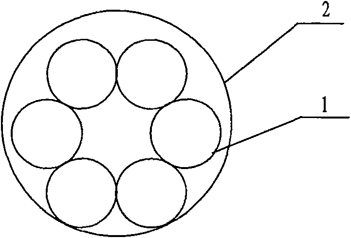
[0023] Figure 5 It is a schematic diagram of the cross-sectional structure of the combined casing heat exchanger in Embodiment 1 of the present invention. As shown in the figure, the casing heat exchanger includes two spiral modules 2, and two casing pipes 3 are arranged in the spiral modules 2 respectively. Firstly, two casing pipes 3 are intertwined with each other over the full length, and then put into the spiral module 2 , and the two spiral modules 2 formed in this way are intertwined with each other over the entire length, and put into the heat exchanger tube bundle 1 .
Embodiment 2
[0025] Figure 6 It is a schematic diagram of the cross-sectional structure of the combined casing heat exchanger in Example 2 of the present invention. As shown in the figure, the casing heat exchanger includes two spiral modules 2, and two casing pipes 3 are arranged in the spiral modules 2 respectively. First, the two sleeves 3 are intertwined with each other over the full length, and then put into the spiral module 2, the two spiral modules 2 formed in this way are intertwined with the two sleeves 3 over the entire length, and put into the heat exchanger tube bundle within 1.
Embodiment 3
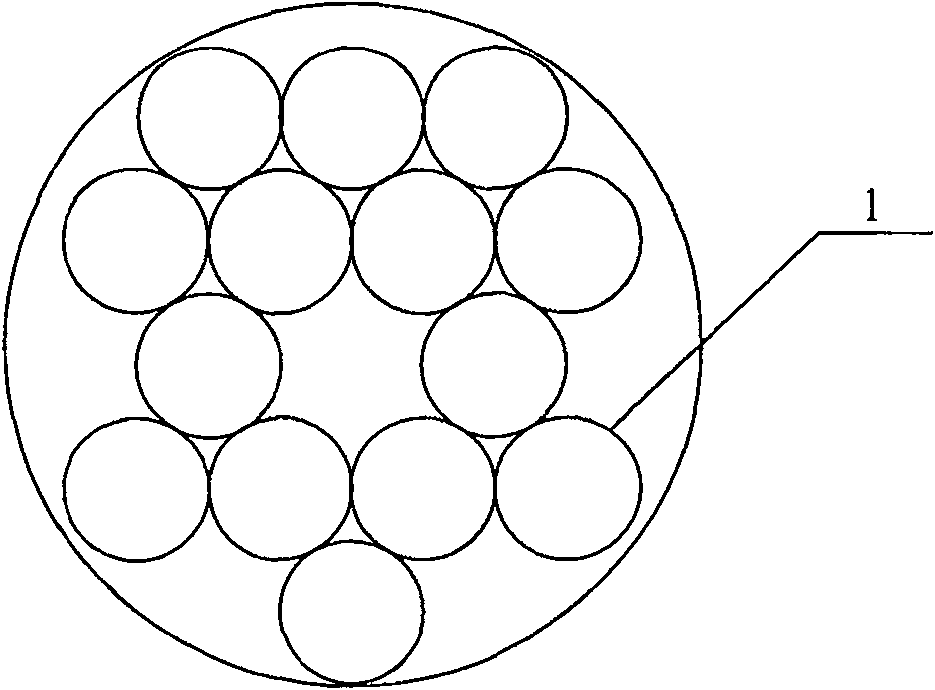
[0027] Figure 7 It is a schematic diagram of the cross-sectional structure of the combined casing heat exchanger in Embodiment 3 of the present invention. As shown in the figure, the casing heat exchanger includes three spiral modules 2, and three casing pipes 3 are arranged in the spiral modules 2 respectively. Firstly, the three casing pipes 3 are intertwined with each other over the full length, and then put into the spiral module 2 , and the three helical modules 2 formed in this way are intertwined with each other over the entire length, and put into the heat exchanger tube bundle 1 .
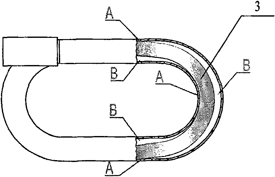
[0028] The helical direction of the helical module 2 of the present invention is opposite to the helical direction of the casing 3 .
[0029] To achieve turbulent flow, it is necessary to achieve the proper Reynolds number, high-speed flow, increased resistance, and increased power consumption. The present invention can achieve a lower flow rate and rely on the internal structure to prom...
PUM
 Abstract
Description
Claims
Application Information