Apparatus, propulsive element and method for processing non-consolidated materials

a propulsive element and non-consolidated material technology, applied in the direction of mixers, gas current separation, sorting, etc., can solve the problem of large turbulence in the main jet portion, and achieve the effect of reducing turbulen

Inactive Publication Date: 2015-02-17
COUTURE MICHEL
View PDF6 Cites 0 Cited by
  • Summary
  • Abstract
  • Description
  • Claims
  • Application Information

AI Technical Summary

Benefits of technology

[0007]In a first broad aspect, the invention provides a propulsive element usable for producing a jet of fluid using a pressurized fluid, the propulsive element comprising: an inlet for receiving the pressurized fluid; a propulsive element passageway extending from the propulsive element inlet; two main outlets in fluid communication with the propulsive element passageway and located substantially opposed to the inlet relative to the propulsive element passageway, the two main outlets being configured and sized such that the two main outlets release each a respective main jet portion when the pressurized fluid is injected in the inlet, the two main jet portions being each substantially divergent, the two main jet portions creating a low pressure zone therebetween; and an auxiliary outlet located between the two main outlets, the auxiliary outlet being in fluid communication with the propulsive element passageway and located substantially opposed to the inlet relative to the propulsive element passageway, the auxiliary outlet being configured and sized such that the auxiliary outlet releases an auxiliary jet portion when the pressurized fluid is injected in the inlet, the auxiliary jet portion being released in the low pressure zone. The auxiliary jet portion has a flow rate, a velocity, a configuration and dimensions such that forces exerted on the two main jet portions by the low pressure zone are reduced by the release of the auxiliary jet portion in the low pressure zone so as to reduce turbulence in the two main jet portions substantially adjacent to the two main outlets.
[0009]Typically, the two main jet portions move at relatively high speed, for example 100 m / s or more, and, in some embodiments, are produced at the two main outlets at supersonic speed. Since the main jet portions move rapidly through ambient air, the low pressure zone is created therebetween. The low pressure zone, in turn, creates relatively large turbulence in the main jet portions. This turbulence slows down the main jet portions relatively quickly. It was found that surprisingly, injecting the auxiliary jet portions that each typically have relatively low speed and relatively low flow rates reduces greatly this turbulence, which allows the main jet portions to merge with each other and form the jet of fluid having relatively large mass flow rate and velocity.
[0010]Advantageously, the proposed propulsive element is manufacturable relatively easily and produces jet of fluids having remarkable properties at relatively low costs and relatively efficiently.
[0011]In another broad aspect, the invention provides a method for producing a jet of fluid using a propulsive element, the propulsive element including two main outlets and an auxiliary outlet located between the two main outlets. The method includes pushing the fluid through the two main outlets to create two main jet portions, the two main jet portions being each substantially divergent, the two main jet portions having a velocity, a configuration and dimensions such that a low pressure zone is created therebetween; and pushing the fluid through the auxiliary outlet to create an auxiliary jet portion, the auxiliary jet portion being released in the low pressure zone, the auxiliary jet portion having a velocity, a configuration, dimensions and a flow rate such that forces exerted on the two main jet portions by the low pressure zone are reduced by the auxiliary jet so as to reduce turbulence in the two main jet portions and increase flow rate, dimensions and speed in the jet of fluid after their unification.

Problems solved by technology

The low pressure zone, in turn, creates relatively large turbulence in the main jet portions.

Method used


Image

  • Apparatus, propulsive element and method for processing non-consolidated materials
  • Apparatus, propulsive element and method for processing non-consolidated materials
  • Apparatus, propulsive element and method for processing non-consolidated materials

Examples


Embodiment Construction

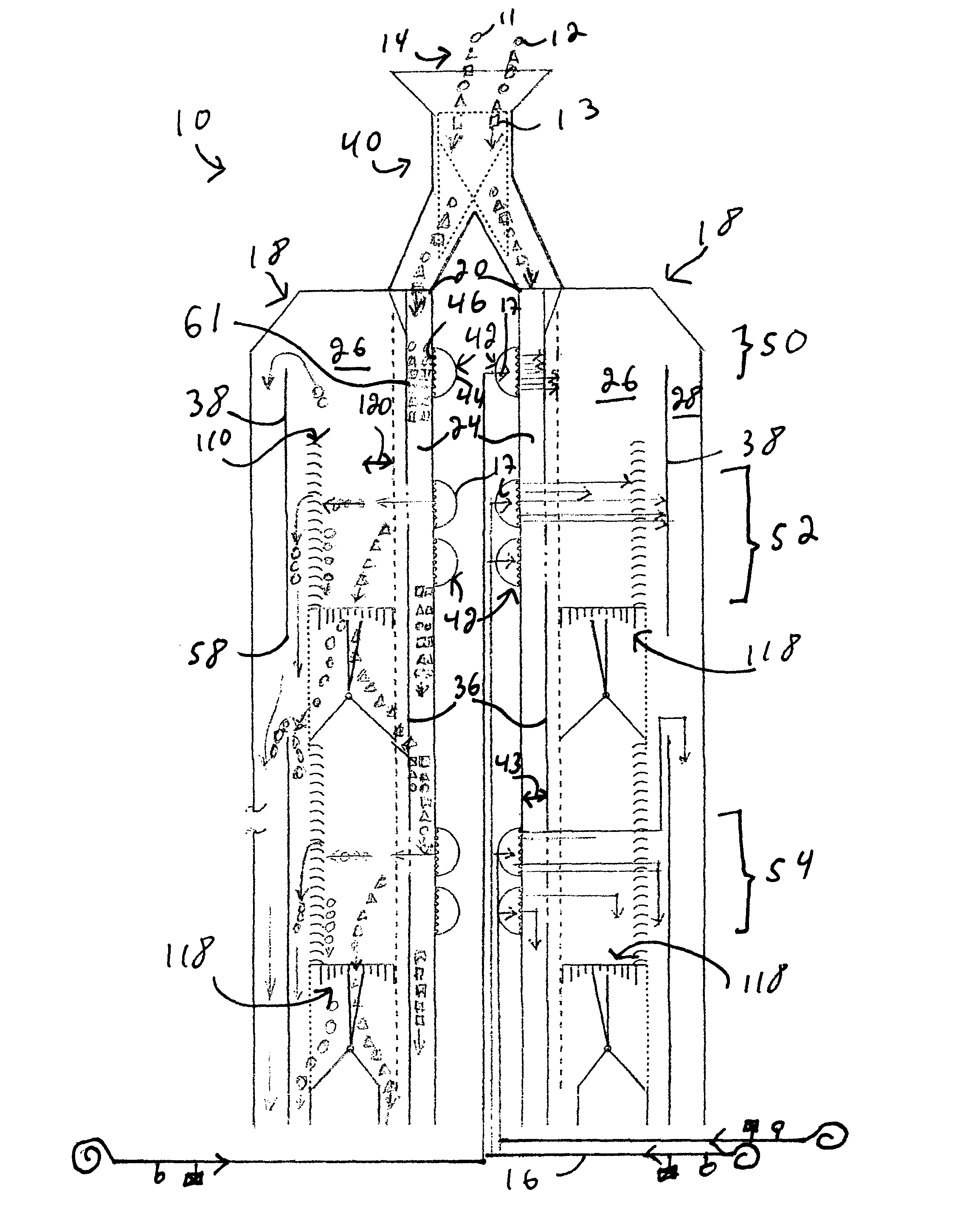
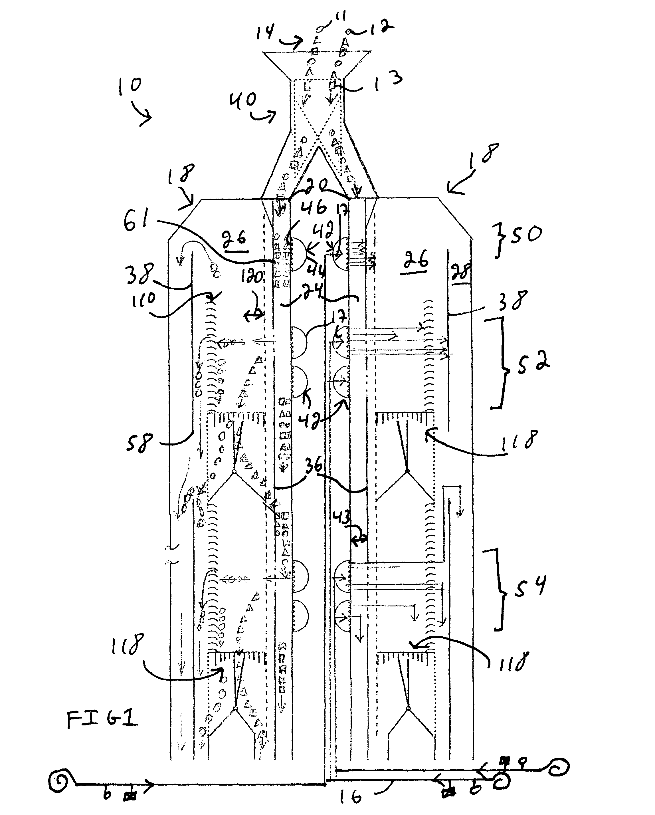
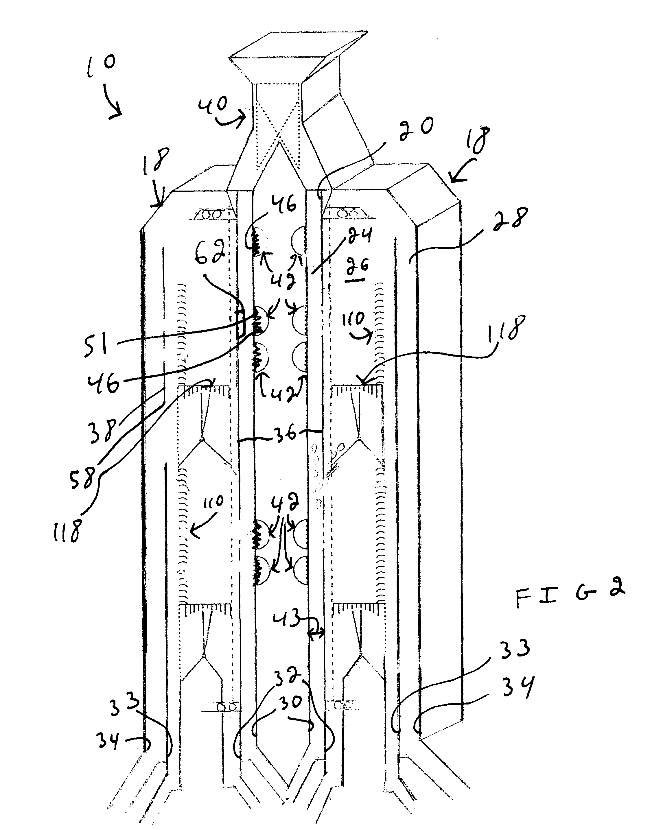
[0049]In this document, side elevation views are shown in most drawings with the understanding that typically, the structures described in this document extend substantially the whole width of the apparatus 10 described herein in a direction perpendicular to the illustrated cross-section. This is illustrated for some structures when comparing FIGS. 1 and 2. Also, directional terminology, such as “up”, “down”“vertical”, and “horizontal” among others, is used in this document for clarity the purposes and relates to the orientation of the apparatus 10 in typical use. This terminology should not be used to restrict the scope of the claimed invention.

[0050]FIG. 1 illustrates an apparatus 10 for processing a non-consolidated material 14. The apparatus 10 is typically manufactured using steel or any impact resistant material able to withstand the forces generated in the apparatus 10 when in use. Here, the non-consolidated material 14 is a granular material shown having three different type...


PUM


Abstract

A propulsive element usable for producing a jet of fluid using a pressurized fluid. An inlet receives the pressurized fluid; a propulsive element passageway extends from the inlet; two main outlets are in fluid communication with the propulsive element passageway and are configured and sized for releasing each a respective main jet portion when the pressurized fluid is injected in the inlet, the two main jet portions being each substantially divergent, the two main jet portions creating a low pressure zone therebetween.

Description

FIELD OF THE INVENTION[0001]The present invention relates to the general field of processes used for processing non-consolidated materials and is particularly concerned with an apparatus, a propulsive element and a method for processing non-consolidated materials.BACKGROUND OF THE INVENTION[0002]There exists a multitude of devices for processing granular and other non-consolidated materials. These devices are used for mixing particles contained in a stream of granular material, separating particles having predetermined properties from a stream of granular material, or treating the granular material by coating constituent particles with a fluid or in any other manner. Some of these devices use a fluid, such as air, blown on the particles to process them. In some cases, devices suck the particles to filtrate or cyclonically process them. A drawback of existing devices is that inhomogeneities in the processed particles create inefficiencies in the process. Another drawback of existing ...

Claims


Application Information

Patent Timeline
Patent Type & Authority Patents(United States)
IPC IPC(8): B07B4/02B01F33/40
CPCB07B4/02B01F5/24B01F13/0227B01F25/80B01F33/404
Inventor COUTURE, MICHEL
Owner COUTURE MICHEL
Why Eureka
Try Eureka