Method, device and system for beamforming smart antenna

A beamforming method and beamforming technology, which are applied in diversity/multi-antenna systems, space transmit diversity, etc., can solve problems affecting system downlink beamforming performance, spatial characteristics and spatial covariance matrix, etc., to achieve good Effects of downlink beamforming, correlation reduction, and aperture reduction

Active Publication Date: 2011-08-31
HENAN INFORMATION CONSULTATION DESIGN & RES
View PDF4 Cites 10 Cited by
  • Summary
  • Abstract
  • Description
  • Claims
  • Application Information

AI Technical Summary

Problems solved by technology

[0005] In view of this, the present invention provides a smart antenna beamforming method, device and system to overcome the high correlation between multipath signals in the prior art, which makes it

Method used


Image

  • Method, device and system for beamforming smart antenna
  • Method, device and system for beamforming smart antenna
  • Method, device and system for beamforming smart antenna

Examples


Embodiment 1

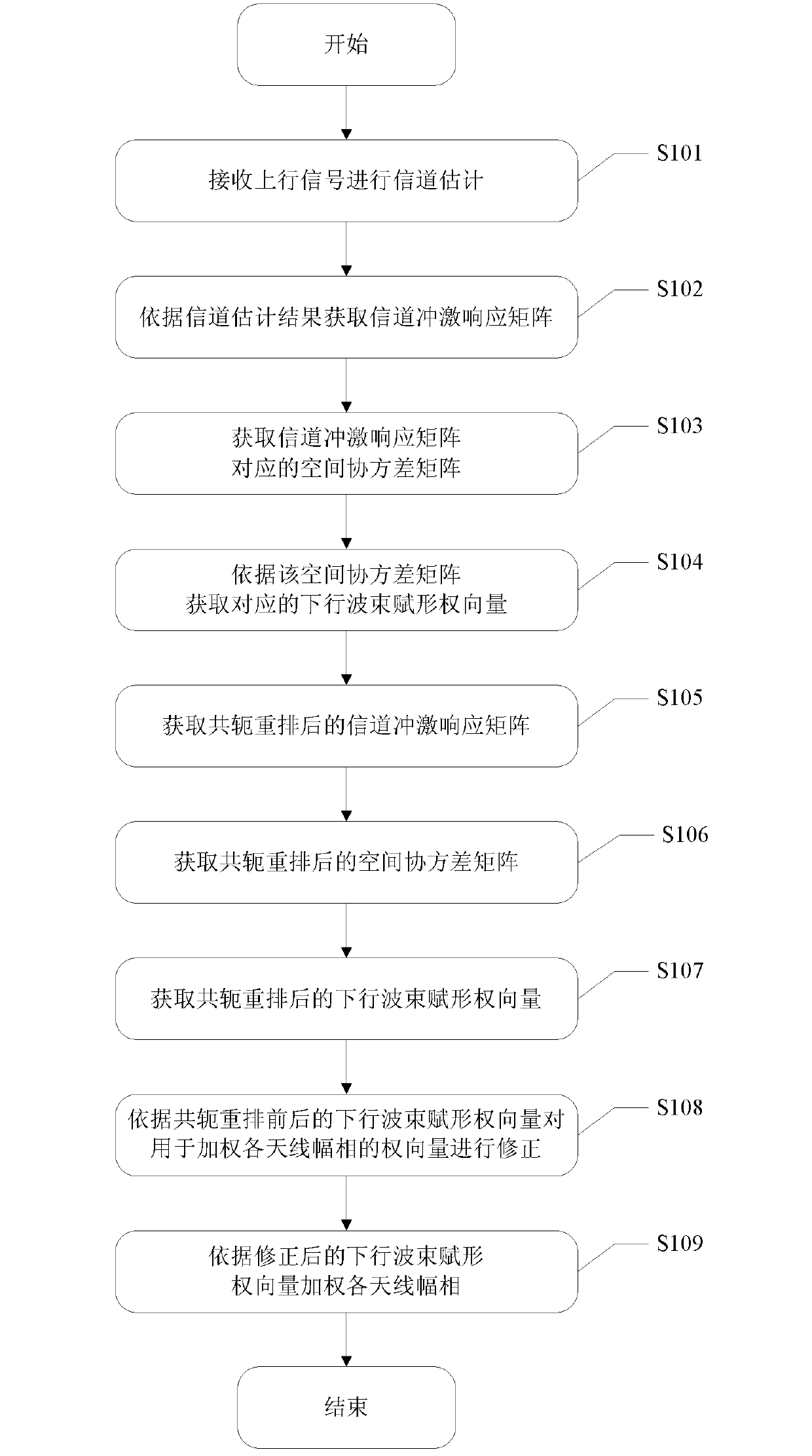
[0068] Please refer to the attached figure 1 , which is a flowchart of a beamforming method for a smart antenna disclosed in an embodiment of the present invention, mainly includes the following steps:

[0069] In step S101, the base station processes the received uplink signal to implement channel estimation for each user on each antenna.

[0070] Step S102, according to the channel estimation results of each user on each antenna, construct a channel impulse response matrix H of each user's array antenna.

[0071] When executing step S101 and step S102, channel estimation is performed for each user, that is, the desired user, and the channel impulse response matrix H of the array antenna of each user is obtained according to the result of channel estimation. Channel model, its mathematical expression is:

[0072] h k ( τ , φ ) = Σ l ...


PUM


Abstract

The invention discloses a method, a device and a system for beamforming a smart antenna. The method comprises the following steps: calculating a downlink beamforming weight vector UR according to a spatial covariance matrix R corresponding to a channel impulse response matrix H acquired in advance; calculating a downlink beamforming weight vector URm according to a spatial covariance matrix Rm corresponding to a channel impulse response matrix Hm determined after the channel impulse response matrix H is rearranged in a conjugated way; determining a corrected downlink beamforming weight vectorby taking the downlink beamforming weight vector UR and downlink beamforming weight vector URm as correct parameters; utilizing a downlink beamforming weight vector U to weight each antenna amplitudephase so as to realize downlink beamforming of a user. The method can reduce multipath signal correlation under the condition of not increasing calculation quantity and not reducing array antenna aperture and can still realize better downlink beamforming even if strong correlative signal exists.

Description

technical field [0001] The present invention relates to the technical field of beamforming in communication technology, and more specifically relates to a beamforming method, device and system for a smart antenna. Background technique [0002] A smart antenna is a two-way antenna, which is mainly used in base stations in order to reduce computational complexity and improve system performance. In fact, it uses the difference in spatial characteristics between different users sharing the same channel to achieve channel multiplication. Users who use the same channel, the same time slot, and the same codeword can achieve user through spatial filtering as long as the spatial characteristics of the signal are different. signal separation. The beamforming method, one of its core technologies in the smart antenna, performs amplitude-phase weighting on the signals received by multiple array antennas to obtain the required antenna beam pointing to achieve spatial separation. [0003...

Claims


Application Information

Patent Timeline
IPC IPC(8): H04B7/06H04B7/08
Inventor 丁婷东方黄冬青王志全崔红涛
Owner HENAN INFORMATION CONSULTATION DESIGN & RES
Why Eureka
Try Eureka