
Apparatus and method for allocating walsh codes to access terminals in an adaptive antenna array CDMA wireless network

a technology of adaptive antenna array and cdma wireless network, applied in diversity/multi-antenna system, multiplex communication, orthogonal multiplex, etc., can solve the problem of reducing the rf capacity, reducing the probability of dropped calls, and affecting the rf capacity. , to achieve the effect of maximizing the re-use of walsh codes

Inactive Publication Date: 2008-08-12
SAMSUNG ELECTRONICS CO LTD
View PDF10 Cites 12 Cited by
  • Summary
  • Abstract
  • Description
  • Claims
  • Application Information

AI Technical Summary

Benefits of technology

[0013]The present invention provides an apparatus and method for using the spatial isolation provided by an adaptive antenna array to maximize the re-use of Walsh codes in a base transceiver subsystem of a wireless network base station. This allows the BTS to support the full capacity of the air interface in adaptive antenna array operation so that the capacity is not constrained by the 64 or 128 Walsh code limit.

Problems solved by technology

However, this technique results in degraded performance and lower-than-expected RF capacity due to requirements for greater Eb / No at the receiver.
However, the result is greater handoff transitions and increased probability of dropped calls.
Those familiar with the art will recognize that doubling the number of sectors does not allow a doubling of Walsh code reuse due to the number of codes required to support soft handoff and due to added overlap regions of adjacent sector antenna patterns.
However, this method is not applicable for an adaptive antenna array base transceiver subsystem (BTS) in which multiple antennas and a baseband AAA processor module are employed per sector.

Method used


Image

  • Apparatus and method for allocating walsh codes to access terminals in an adaptive antenna array CDMA wireless network
  • Apparatus and method for allocating walsh codes to access terminals in an adaptive antenna array CDMA wireless network
  • Apparatus and method for allocating walsh codes to access terminals in an adaptive antenna array CDMA wireless network

Examples


Embodiment Construction

[0031]FIGS. 1 through 4, discussed below, and the various embodiments used to describe the principles of the present invention in this patent document are by way of illustration only and should not be construed in any way to limit the scope of the invention. Those skilled in the art will understand that the principles of the present invention may be implemented in any suitably arranged wireless network base station.

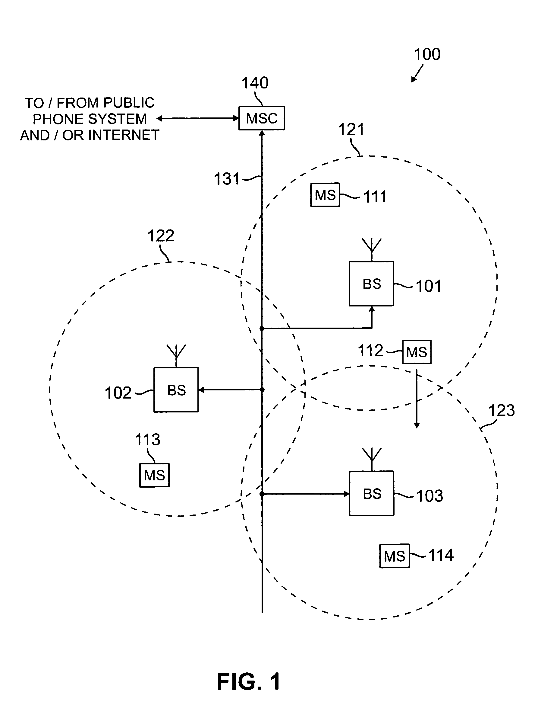
[0032]FIG. 1 illustrates exemplary wireless network 100 according to one embodiment of the present invention. Wireless network 100 comprises a plurality of cell sites 121-123, each containing one of the base stations, BS 101, BS 102, or BS 103. Base stations 101-103 communicate with a plurality of mobile stations (MS) 111-114 over, for example, code division multiple access (CDMA) channels. Mobile stations 111-114 may be any suitable wireless access terminals, including conventional cellular phones, PCS handset devices, personal digital assistants, portable computers, or ...


PUM


Abstract

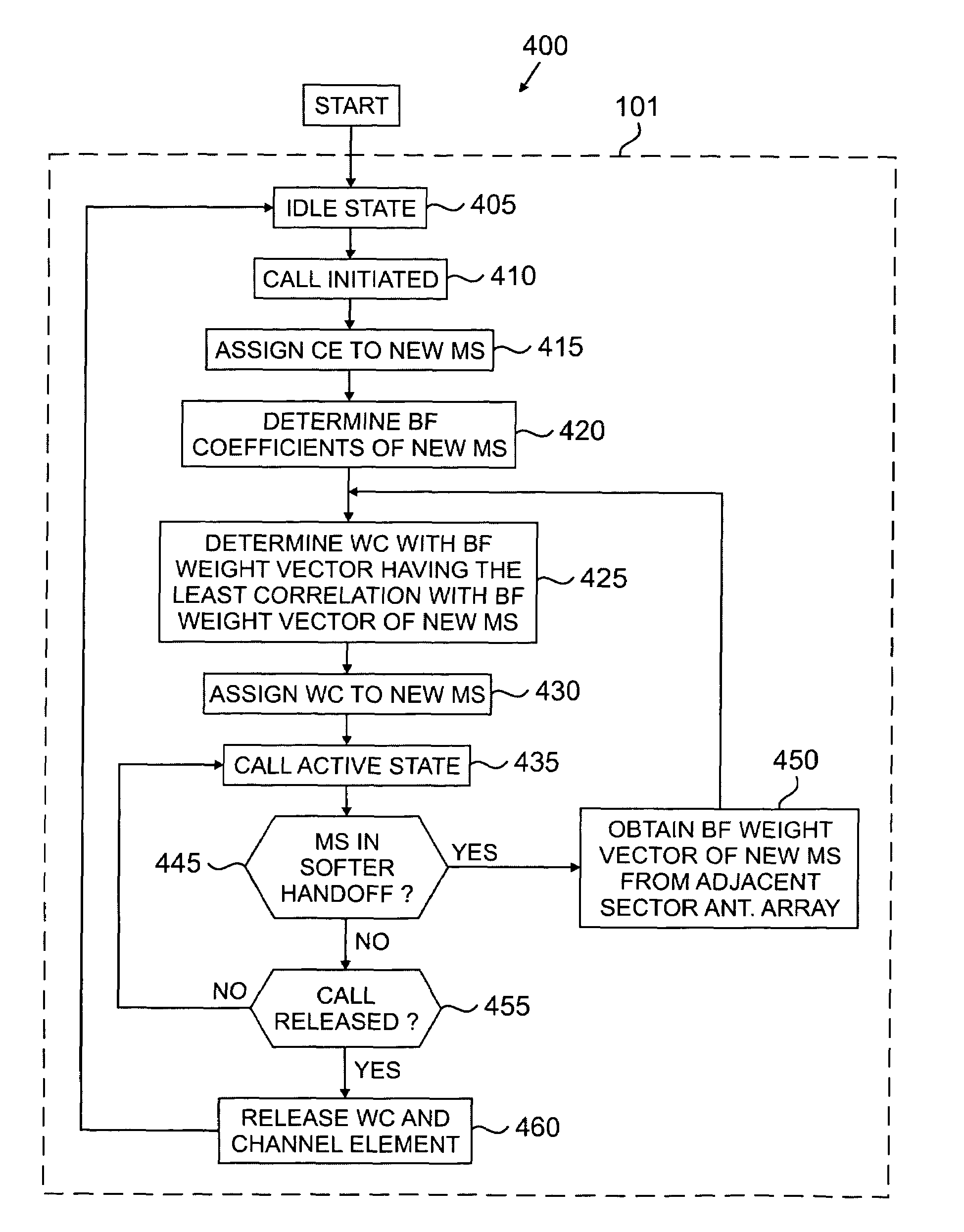
An apparatus having: 1) a database for storing R active wireless terminal records, each of the R active wireless terminal records containing: a) an active orthogonal code and b) corresponding downlink beamforming coefficients used to communicate with one of the wireless access terminals; and 2) a controller associated with the database that receives a notification that a new wireless access terminal is accessing the base station and, in response to the notification, compares each of the R active wireless terminal records to new downlink beamforming coefficients associated with the new wireless access terminal. The controller determines at least one active wireless terminal record containing corresponding downlink beamforming coefficients that have the least correlation with the new downlink beamforming coefficients.

Description

[0001]The present invention claims priority to U.S. Provisional Application Ser. No. 60 / 282,059 filed Apr. 6, 2001.TECHNICAL FIELD OF THE INVENTION[0002]The present invention is directed, in general, to digital communication systems and, more specifically, to an apparatus and method for dynamic allocation of Walsh codes in an adaptive antenna array (AAA) CDMA base transceiver station (BTS) utilizing spatial diversity for communications links with mobile users to support a traffic channel count greater than the Walsh code limit such as that found 2G (IS-95) systems, with a limit of 64, or in 3G (IS2000) systems, with limits of either 64 or 128.BACKGROUND OF THE INVENTION[0003]The radio frequency (RF) spectrum is a limited commodity. Only a small portion of the spectrum can be assigned to each communications industry. The assigned spectrum, therefore, must be used efficiently in order to allow as many frequency users as possible to have access to the spectrum. Multiple access modulati...

Claims


Application Information

Patent Timeline
IPC IPC(8): H04J11/00H04B1/707H04B7/06H04B7/26H04J13/00H04J13/18
CPCH04B7/0617H04J13/18H04J13/0048H04B1/707H04B7/2628
Inventor KAVAK, ADNANCLEVELAND, JOSEPH R.
Owner SAMSUNG ELECTRONICS CO LTD
Learn More