Motor

a technology of fluid pressure actuation and motor, which is applied in the direction of reciprocating piston engines, engines with rotating cylinders, and positive displacement engines, etc., can solve the problem of a fairly complex valve actuation mechanism of the motor

Inactive Publication Date: 2005-01-11
POWERVERDE
View PDF9 Cites 19 Cited by
  • Summary
  • Abstract
  • Description
  • Claims
  • Application Information

AI Technical Summary

Problems solved by technology

That motor employs a fairly complex valve actuating mechanism including linkages between the valves for one set of cylinders and the Scotch yoke of the other set of cylinders.

Method used


Image

  • Motor
  • Motor
  • Motor

Examples


Embodiment Construction

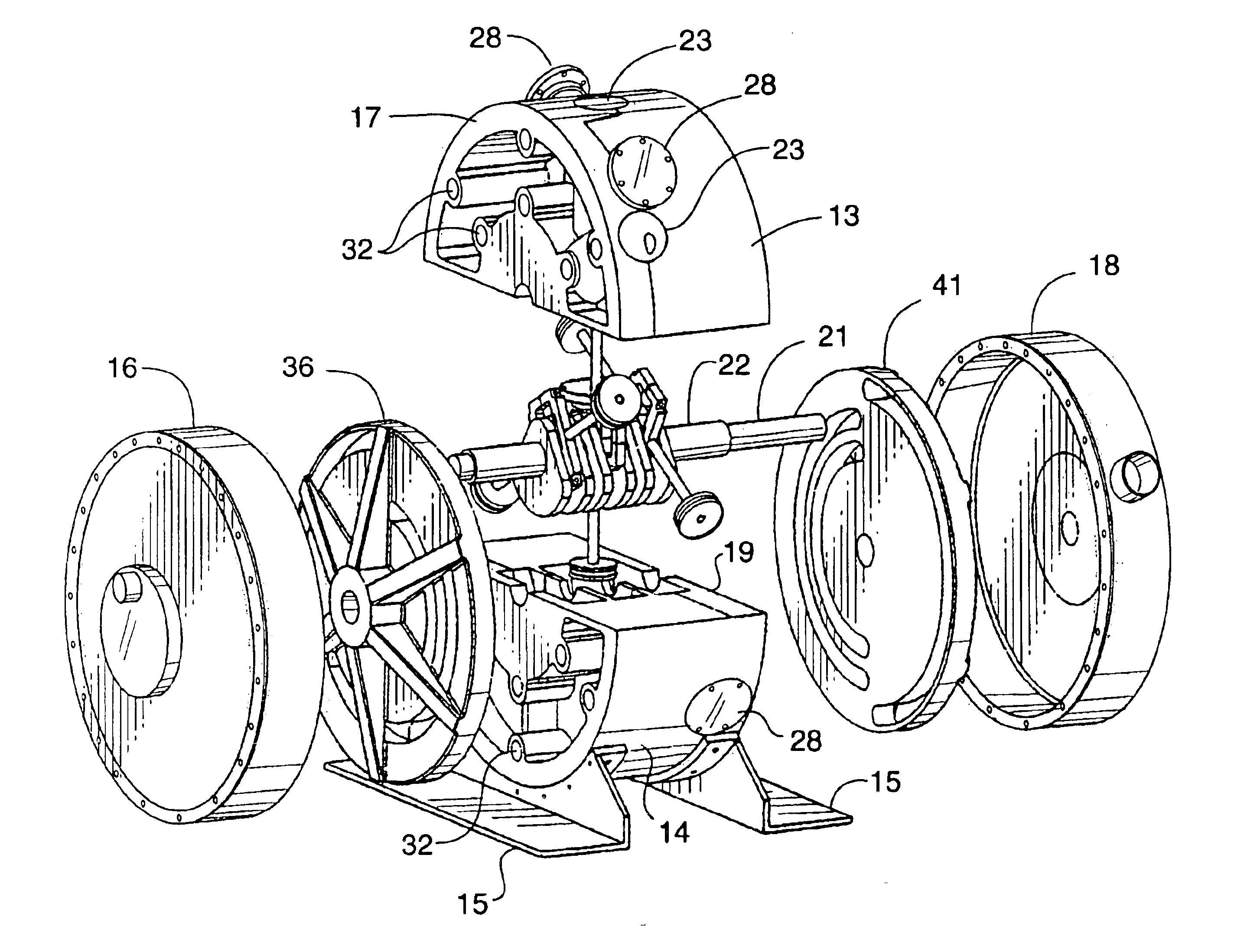
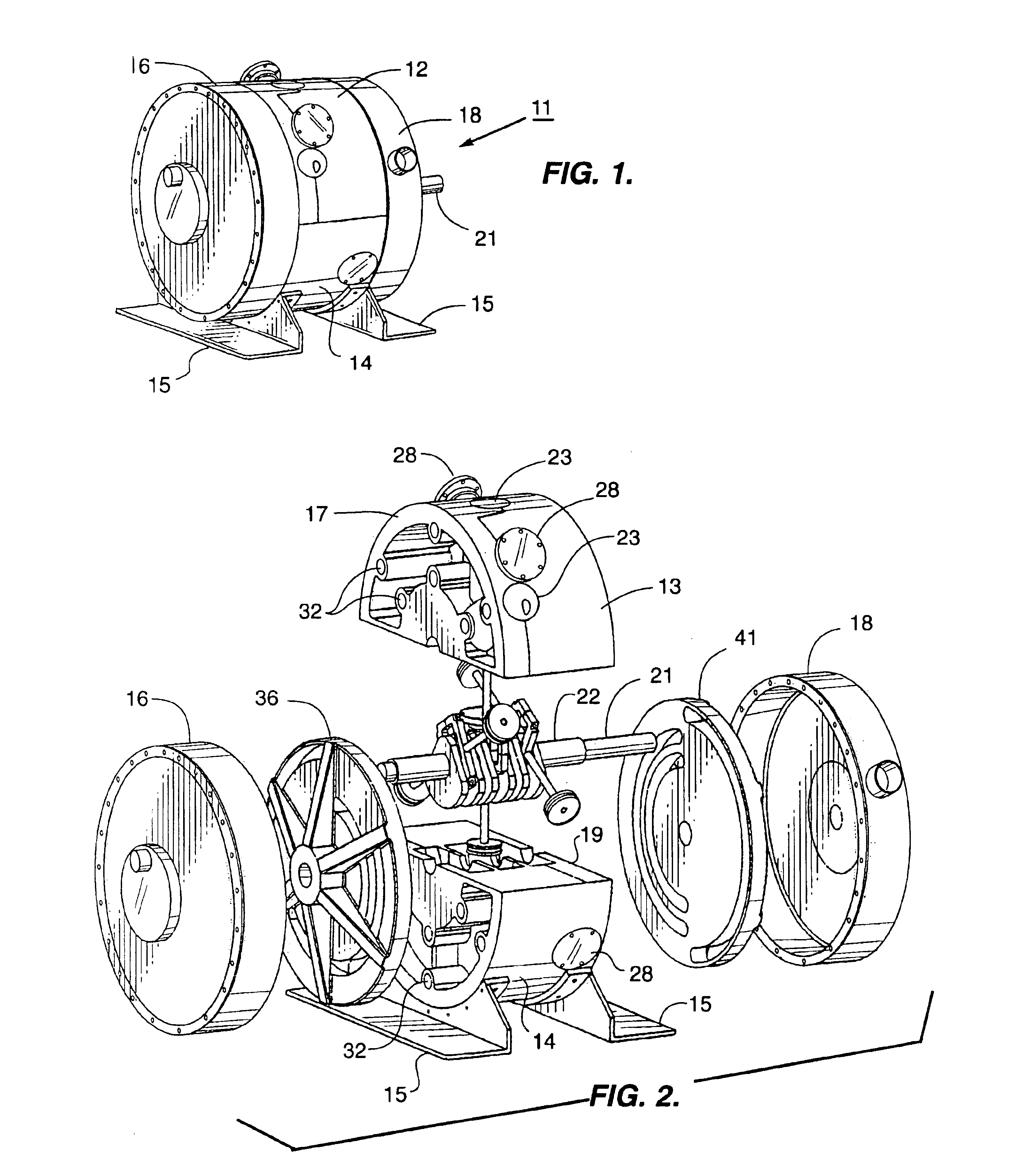
In FIG. 1 reference numeral 11 designates generally a fluid pressure actuated motor employing this invention. The motor 11 has a split two-piece cylinder block 12 having an upper portion 13 and a lower portion 14. The motor may have feet 15 attached to the cylinder block lower portion 14 for mounting the motor.

As best shown in FIGS. 1 and 2 the motor 11 further comprises an intake cover 16 over the intake face 17 of cylinder block 12 and an exhaust cover 18 over the exhaust face 19 of the cylinder block.

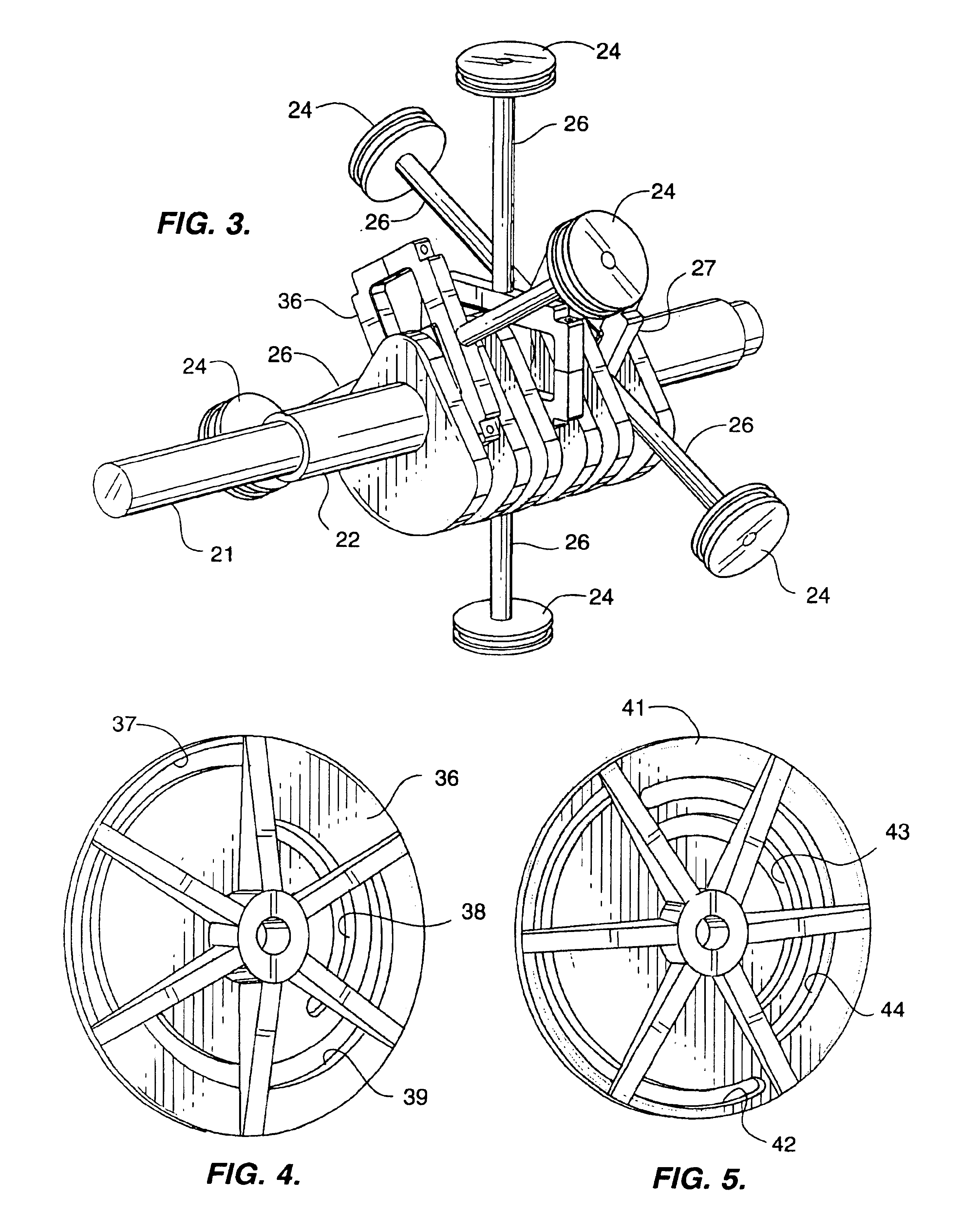
Protruding from one end of the motor 11 is a drive portion 21 of a crankshaft 22 axially positioned for rotation within cylinder block 12. Drive portion 21 of the crankshaft is adapted to be coupled to another appliance, such as a generator, for driving the latter.

Although the principles of this invention are applicable to a fluid pressure motor having but one set of opposed cylinders multiple sets are preferred to increase the output of the motor. In the embodiment illustrated and p...


PUM


Abstract

A push-push type fluid pressure actuated motor has one or more radial opposed cylinder sets each having a pair of pistons, a connecting rod, and a Scotch-yoke connection to a crankshaft. An intake rotor valve at one face of the cylinder block and an exhaust rotor valve at an opposite face of the cylinder block are mounted on and rotate with the crankshaft. The rotor valves admit pressurized fluid to the cylinder and allow discharge of spent fluid from the cylinders.

Description

TECHNICAL FIELDThis invention is directed to improvements in fluid pressure actuated motors.BACKGROUND ARTThere are many applications for a motor operating on a pressurized fluid. That fluid may, for example, be air, natural gas, carbon dioxide or a vaporizable liquid in an Organic Rankine Cycle system.Particularly suited for many such applications is the, so called, “push-push” radial reciprocating motor. This type of motor has a set of two opposed cylinders with a crankshaft midway between the cylinders. Pistons in the cylinders are connected to the crankshaft by a common connecting rod having a Scotch yoke engaging the crank pin. A valving arrangement driven by the crankshaft directs pressurized fluid to the top of one piston and to the bottom of the other during a half revolution of the crankshaft. During the succeeding half revolution of the crankshaft pressurized fluid is directed to the top of the other piston and the bottom of the one piston. Thus, the crankshaft is propelle...

Claims


Application Information

Patent Timeline
Patent Type & Authority Patents(United States)
IPC IPC(8): F01B1/00F01B9/02F01B1/06F01B9/00
CPCF01B1/062F01B9/023F01B1/0627
Inventor BARKER, FRED B.KONRAD, GEORGE
Owner POWERVERDE
Why Eureka
Try Eureka