Multi-stage backrest assembly

a backrest and multi-stage technology, applied in the field of multi-stage backrest assemblies, can solve the problem of user easily feeling uncomfortable during a long period of time, and achieve the effect of comforting the user

Active Publication Date: 2005-01-18
WU YAO CHUAN
View PDF12 Cites 89 Cited by
  • Summary
  • Abstract
  • Description
  • Claims
  • Application Information

AI Technical Summary

Benefits of technology

The primary objective of the present invention is to provide a multi-stage backrest assembly having a pivotable function so as to fit the curve of the user's body ergonomically, thereby providing a comfortable effect to the user.

Problems solved by technology

However, the conventional backrest 8 has a fixed structure and cannot be adjusted so as to fit the curve of the user's body ergonomically, so that the user easily feels uncomfortable during a long period of time.

Method used


Image

  • Multi-stage backrest assembly
  • Multi-stage backrest assembly
  • Multi-stage backrest assembly

Examples


Embodiment Construction

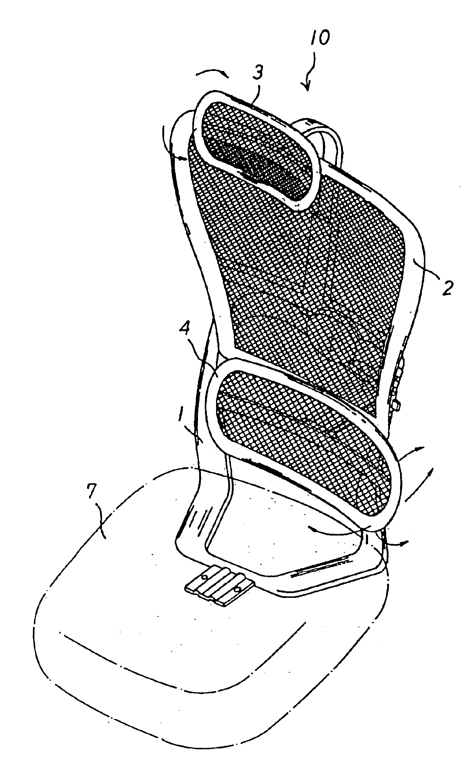
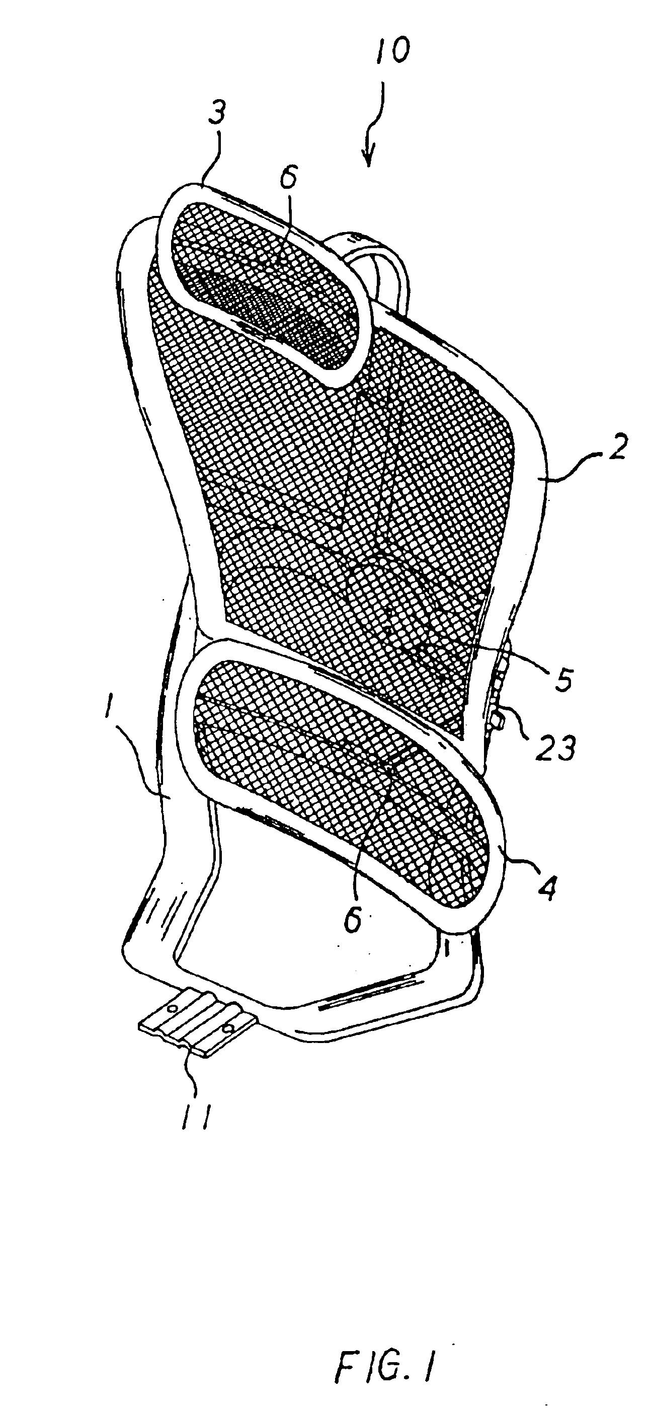
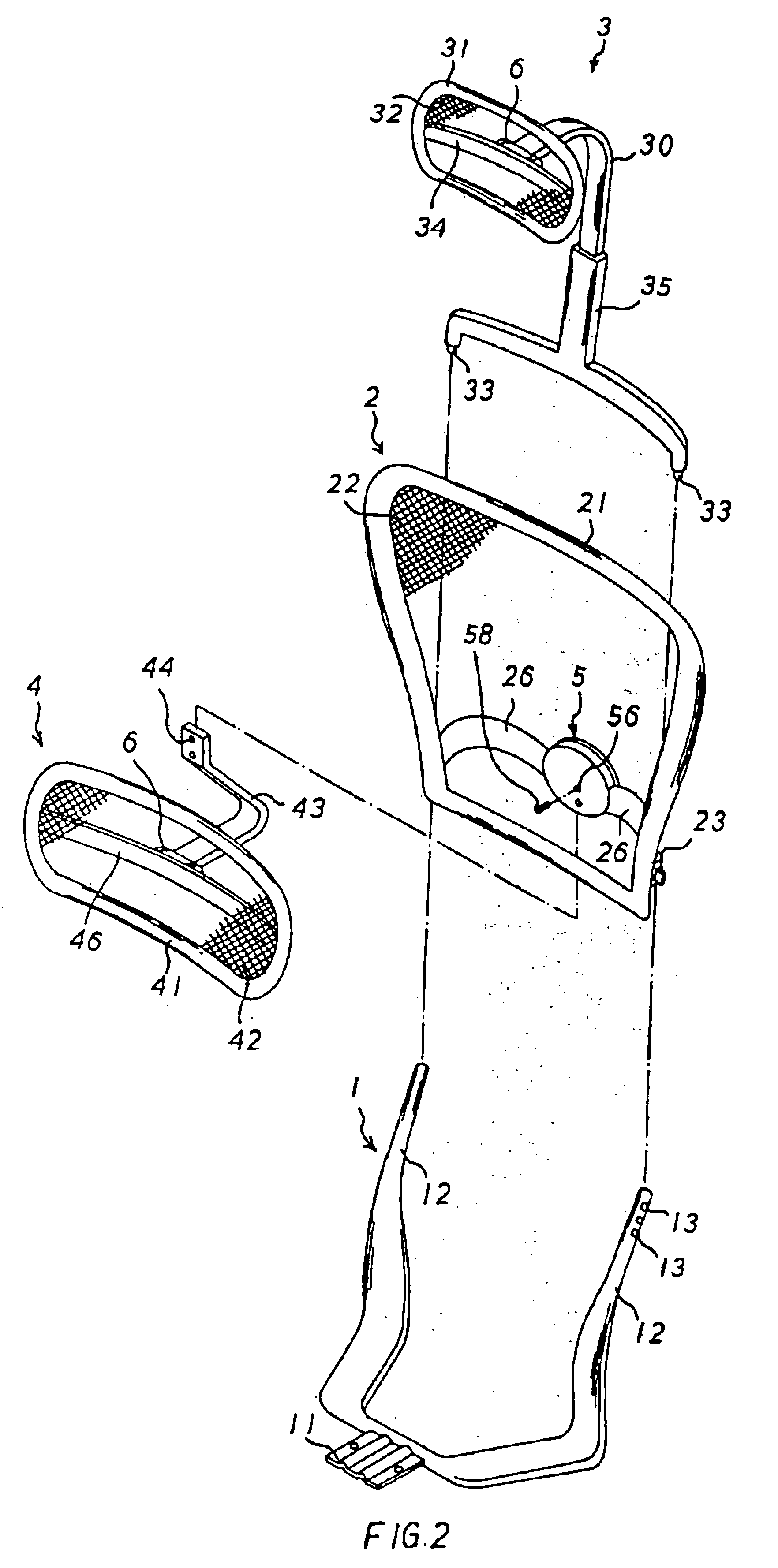
Referring to the drawings and initially to FIGS. 1-5, a multi-stage backrest assembly 10 for a chair in accordance with the preferred embodiment of the present invention comprises a support frame 1, a back plate 2, a head plate 3, a waist plate 4, a first elastic swivel device 5, and two second elastic swivel devices 6.

The support frame 1 is substantially U-shaped and has two substantially L-shaped sections each having a distal end formed with a support tube 12 formed with a plurality of locking holes 13. The support frame 1 has a mediate portion formed with a fixing plate 11 mounted on a seat 7 (see FIG. 6), so that the multi-stage backrest assembly 10 is mounted on the seat 7.

The back plate 2 is mounted on the support frame 1 and includes a backrest frame 21, a net 22 made of foam material or the like mounted on the backrest frame 21, two locking tubes 23 mounted on two sides of the backrest frame 21 and each mounted on the respective support tube 12 of the support frame 1, two cr...


PUM


Abstract

A multi-stage backrest assembly includes a support frame, a back plate, a head plate, a waist plate, a first elastic swivel device, and two second elastic swivel devices. Thus, the multi-stage backrest assembly has a pivotable function so as to fit the curve of the user's body ergonomically, thereby providing a comfortable effect to the user.

Description

BACKGROUND OF THE INVENTION1. Field of the InventionThe present invention relates to a multi-stage backrest assembly, and more particularly to a multi-stage backrest assembly for a chair.2. Description of the Related ArtA conventional backrest 8 for a chair in accordance with the prior art shown in FIG. 7 comprises a main body 80 made of foam material and formed with a fixing plate 82 secured on a seat (not shown) for mounting the main body 80 of the backrest 8 to the seat. However, the conventional backrest 8 has a fixed structure and cannot be adjusted so as to fit the curve of the user's body ergonomically, so that the user easily feels uncomfortable during a long period of time.SUMMARY OF THE INVENTIONThe primary objective of the present invention is to provide a multi-stage backrest assembly having a pivotable function so as to fit the curve of the user's body ergonomically, thereby providing a comfortable effect to the user.Another objective of the present invention is to prov...

Claims


Application Information

Patent Timeline
Patent Type & Authority Patents(United States)
IPC IPC(8): A47C7/36A47C7/38A47C7/46
CPCA47C7/38A47C7/46A47C7/405
Inventor WU, YAO-CHUAN
Owner WU YAO CHUAN
Why Eureka
Try Eureka