Slideable vascular filter

a vascular filter and slide technology, applied in the field of medical devices, can solve the problems of inaccurate deployment, cumbersome use, and the filter generally has not proven to be exceptionally effective in actual use, and achieve the effect of convenient deployment and retracting

Inactive Publication Date: 2005-01-18
TYCO HEALTHCARE GRP LP
View PDF13 Cites 236 Cited by
  • Summary
  • Abstract
  • Description
  • Claims
  • Application Information

AI Technical Summary

Benefits of technology

The present invention provides a medical device which can easily be deployed and retracted during a minimally invasive medical procedure. In one preferred embodiment, the medical device may take the form of a filter useful in any channel of a patient's body, be it in a blood vessel, urinary tract, or other type of vessel.

Problems solved by technology

However, most such filters generally have not proven to be exceptionally effective in actual use.
These filters tend to be cumbersome to use and accurate deployment is problematic because if they are not properly seated in the vessel they can drift to a more distal site where they are likely to do more harm than good.
In addition, these filters are generally capable of only trapping relatively large thrombi and are not effective for removing smaller embolic particles from the blood stream.
The problems with most temporary filters, which are intended to be used only during a particular procedure then retracted with the thrombi trapped therein, are more pronounced.
Even If the trap does effectively capture the dislodged material, it has proven to be relatively difficult or complex to retract the trap back into the catheter through which it was delivered without simply dumping the trapped thrombi back into the blood stream, defeating the purpose of the temporary filter device.
Some medical devices are also permanently deployed in a patient's vessel, but properly positioning these devices at the desired treatment site using minimally invasive techniques can be cumbersome.
When deploying these occlusion devices through a delivery catheter, though, the friction between the occlusion device and the wall of the catheter can make it difficult to deploy the device at a precisely selected location.
These problems are even more pronounced in longer catheters tracking through more tortuous paths.

Method used


Image

  • Slideable vascular filter
  • Slideable vascular filter
  • Slideable vascular filter

Examples


Embodiment Construction

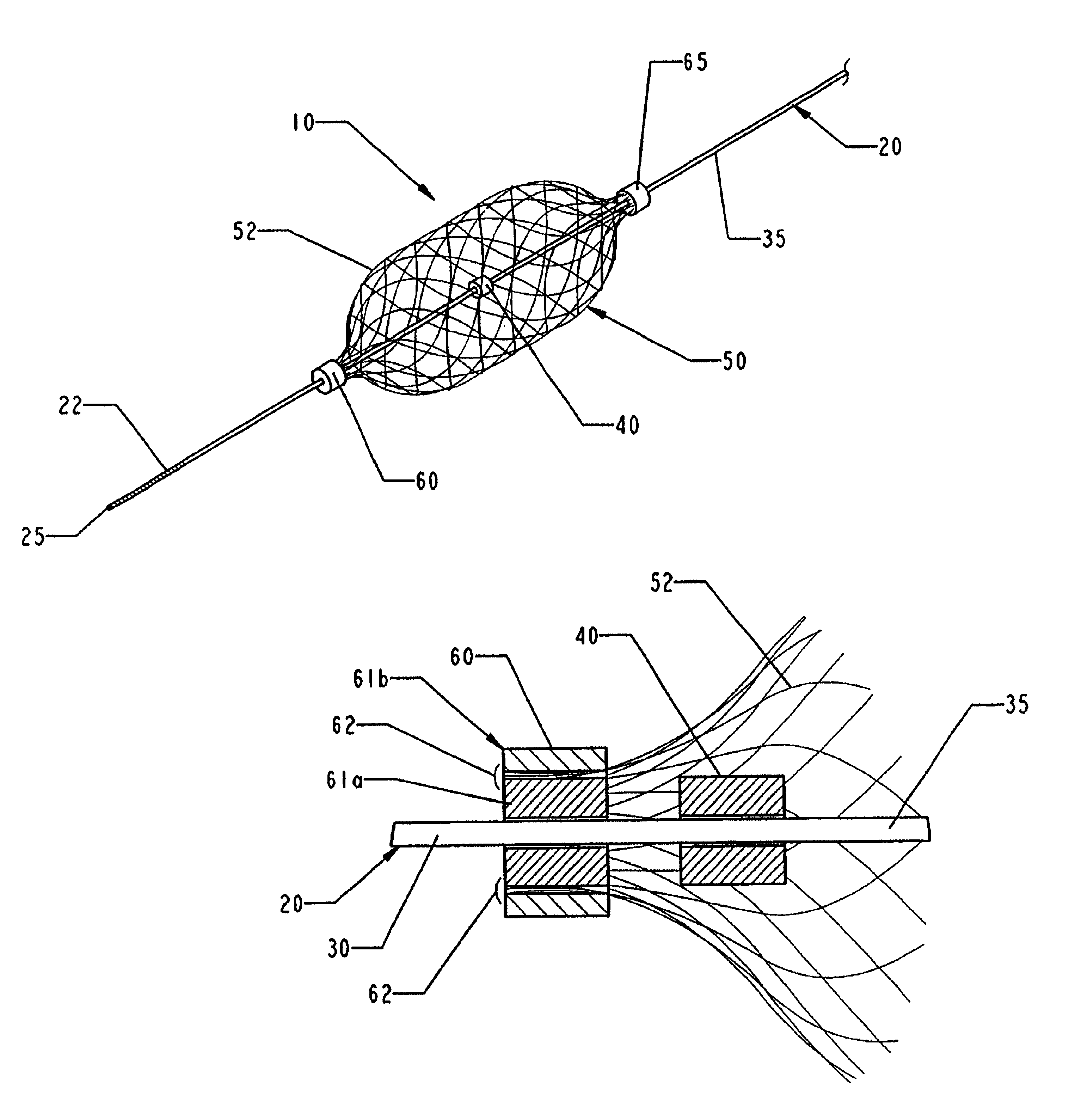
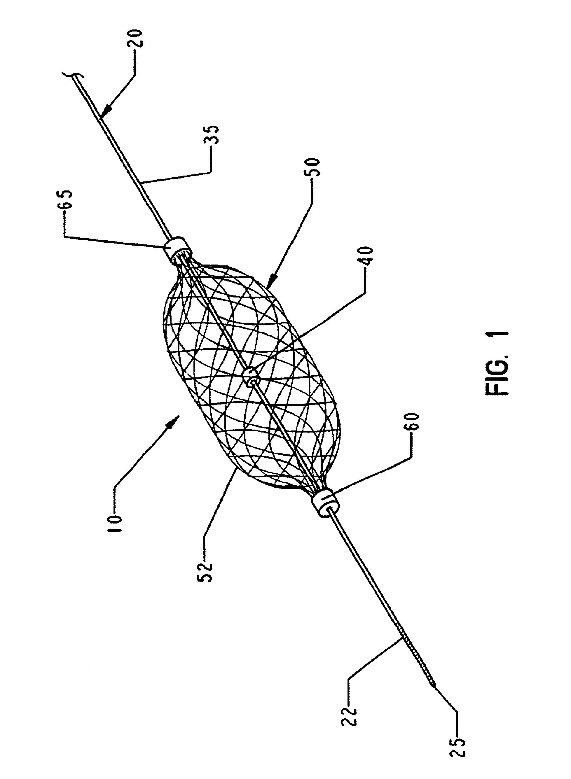
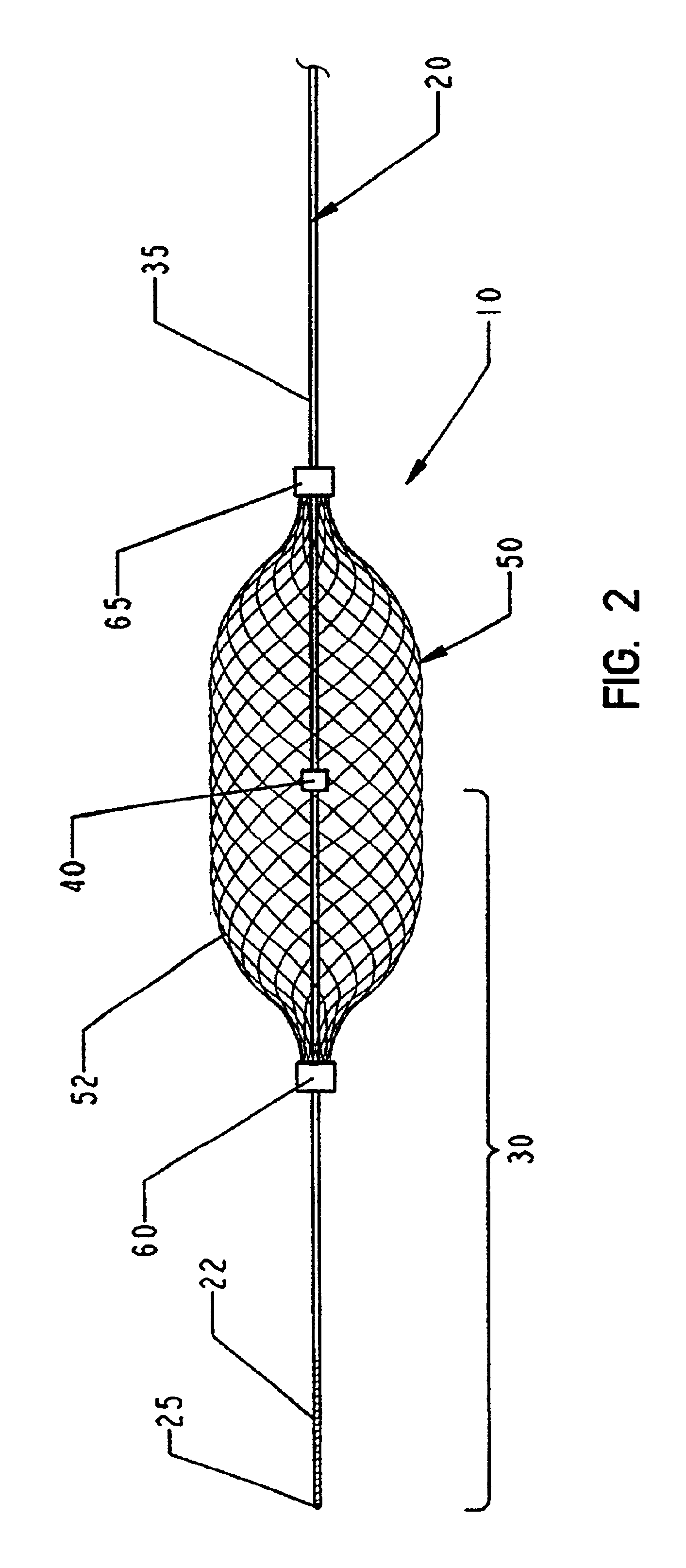
FIGS. 1 and 2 are schematic illustrations of one medical device in accordance with the present invention. This medical device comprises a filter system 10 which can be deployed in a channel in a patient's body. As noted above, this filter can be used in any channel in a patient's body, including blood vessels, the urinary tract or biliary tract and airways. This filter system 10 is optimally designed to be deployed in a patient's vessel in a minimally invasive procedure, such as by introducing the filter system into a blood vessel through an introducing catheter (not shown in FIGS. 1 and 2).

The filter system 10 of the invention generally includes a mandrel 20 and a filter 50. Conceptually, the mandrel 20 can be thought of as having a primary function of positioning and controlling the deployment of the filter 50 while the filter can be considered the primary therapeutic or functional element of the system 10.

The mandrel 20 should be fairly flexible to allow the device to be deployed...


PUM


Abstract

A collapsible medical device for use, e.g., as a vascular filter. The device includes a mandrel having a distal end and a stop spaced proximally of the distal end. A proximal length of the mandrel extends proximally of the stop and a distal length of the mandrel extends distally of the stop. A functional element (e.g., a vascular filter) has a radially expandable body and includes a proximal slider and a distal slider. The proximal and distal sliders are slidable along the mandrel independently of one another such that the distance between the proximal slider and distal slider can be varied to effect different configurations of the functional element. In one method of using such a device, the functional element is urged distally to a treatment site by urging the mandrel distally. This causes the stop to exert a distal biasing force on the distal slider, which acts against a restorative force of the functional element to axially elongate the functional element and reduce friction between the functional element and a wall of the vessel.

Description

FIELD OF THE INVENTIONThe present invention provides a medical device which can employed in a minimally invasive medical procedure, e.g., by deploying it in a blood vessel through a catheter. While a variety of such medical devices can be made in accordance with the invention, the invention is particularly useful as a filter for use in a blood vessel or other channel in a patient's body.BACKGROUND OF THE INVENTIONFilters can be deployed in channels or vessels in patient's bodies in a variety of medical procedures or in treating certain conditions. For example, rotating burrs are used in removing atheroma from the lumen of patients' blood vessels. These burrs can effectively dislodge the atheroma, but the dislodged material will simply float downstream with the flow of blood through the vessel. Filters can be used to capture such dislodged material before it is allowed to drift too far downstream, possibly occluding blood flow through a more narrow vessel.Some researchers have propos...

Claims


Application Information

Patent Timeline
Patent Type & Authority Patents(United States)
IPC IPC(8): A61F2/01A61B17/12A61B17/00A61F2/00
CPCA61F2/01A61F2/013A61F2230/0006A61F2250/0098A61F2002/011A61F2/011A61F2/0108A61F2002/016
Inventor KUSLEIKA, RICHARD S.FINANDER, BRIAN V.
Owner TYCO HEALTHCARE GRP LP
Why Eureka
Try Eureka