System and method for fast dynamic link adaptation

a dynamic link and adaption technology, applied in power management, multiplex communication, high-level techniques, etc., can solve the problems of increasing the probability of transmitting data not being received, reducing the efficiency of tfcs, and increasing the error rate. achieve the effect of efficient reduction of tfcs

Inactive Publication Date: 2005-01-18
RAKUTEN GRP INC
View PDF7 Cites 42 Cited by
  • Summary
  • Abstract
  • Description
  • Claims
  • Application Information

AI Technical Summary

Benefits of technology

The present invention is system and method for enabling efficient reduction of TFCs in the TFCS to support a desired transmission, while remaining within power and data requirements. In the event that the UE transmission power requirements exceed the maximum or allowable transmission power, the set of TFCs is reduced to only those acceptable TFCs that currently do not exceed the power limit. The UE will then chose from among the acceptable reduced set of TFCs.
The invention also supports advanced determination of non-supported TFCs. The TFCs that require transmission power greater then the maximum or allowed UE transmission power shall be determined continuously in every TTI, not just in TTIs where the maximum power has been exceeded. The TFC selection process is adjusted to avoid selection of TFCs that exceed transmission power capabilities in advance of transmission.
The present invention also enables the restoration of the TFCs in the TFCS when the maximum power condition no longer exists.

Problems solved by technology

When these signals are transmitted at the maximum power level (which is less than their desired transmit power level) they experience degraded performance and have increased error rates, increasing the likelihood that the transmitted data will not be received, and that the system resources being used are being wasted.
This ultimately results in undesirable system performance, since the transmission will be made at a power level that is not adequate to maintain the desired level of error rate performance.
This effect is considered to be unavoidable for the period from when the maximum power condition is perceived to when the UL transmissions can be reconfigured to a reduced overall rate.
There is strong motivation to exceed the specified requirements since transmissions that require a power level greater than the maximum transmit power level are likely to fail.
Services that allow for data retransmission of failed transmissions result in increased overhead, reduced radio resource efficiency and reduced UE battery life.
Services that do not allow for retransmission result in an increase in the BLER, thereby causing subsequent increased power requests to attempt to maintain the BLER quality target.
Since the UE is already transmitting at its maximum power, an increase in signal to interference ratio SIR target used in the UL transmit power control algorithm does not improve the BLER performance for the current channel conditions.
If the channel conditions improve, the increased SIR target will require the UE to transmit at a power level greater than necessary to maintain the desired performance, resulting in reduced radio resource efficiency and battery life.
There are, however serious drawbacks with the current manner in which TFCs are removed.
However, there is no guarantee that the reduced set of TFCs will not require power in excess of the maximum power.
This results in another iteration of the process, and an additional delay, to further reduce the set of TFCs.
Ultimately, the performance of the system is degraded during the maximum power condition.
Additional performance concerns arise when the UE is attempting to recover the TFCs that have been blocked due to the maximum power condition.
Accordingly, the prior art methods of handling the situation where the UE is in its maximum power state fall far short of acceptable system performance.

Method used


Image

  • System and method for fast dynamic link adaptation
  • System and method for fast dynamic link adaptation
  • System and method for fast dynamic link adaptation

Examples


Embodiment Construction

)

The present invention will be described with reference to the drawing figures wherein like numerals represent like elements throughout.

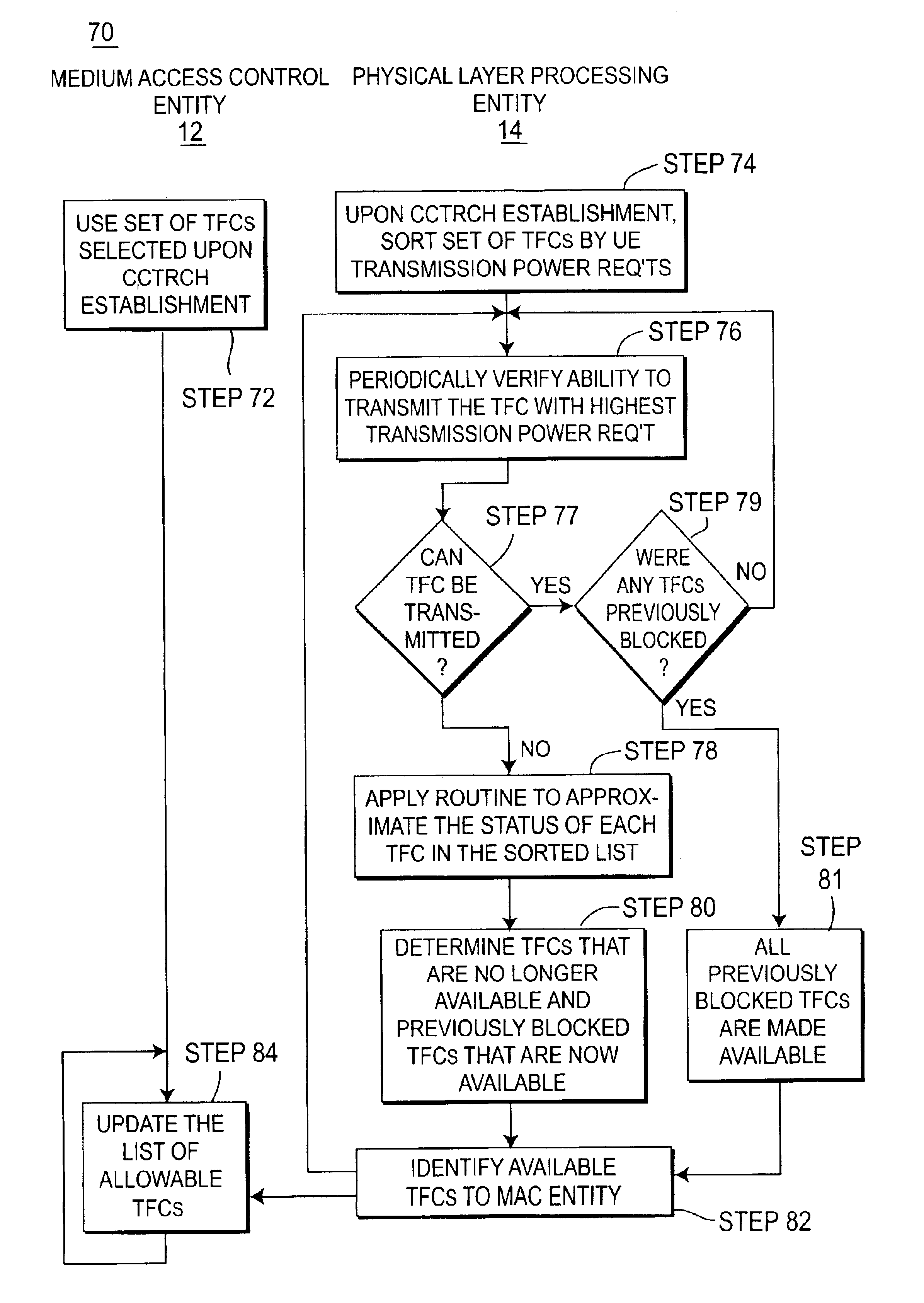
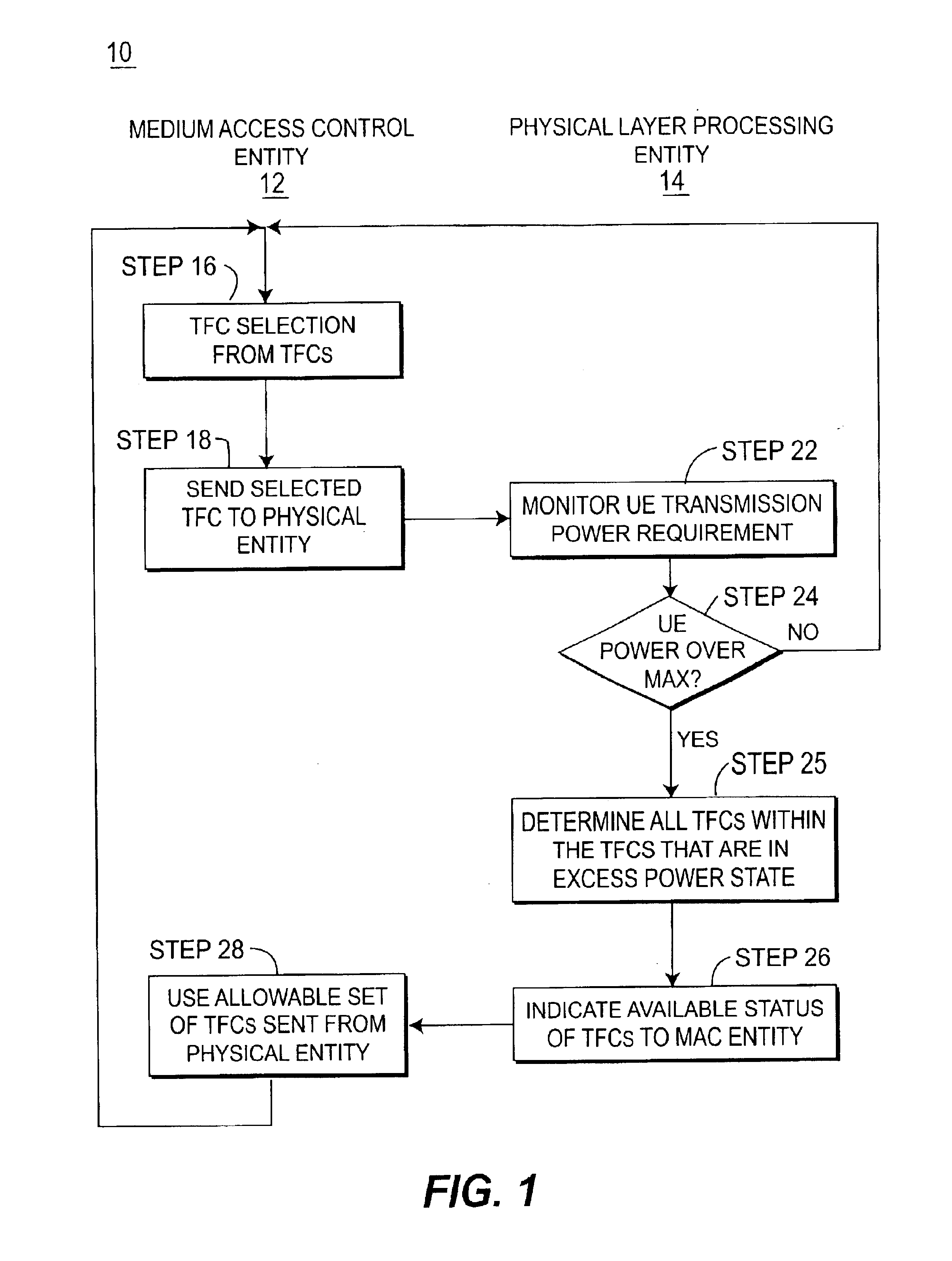
There are three basic aspects to dynamic link adaption in accordance with the present invention. First, when a condition exists where the UE transmission power requirement exceeds the maximum, or maximum allowed, power of the UE, the TFCs that require power in excess of the maximum power limit are efficiently blocked. The MAC is informed, for subsequent TFC selection, of all TFCs that currently exceed this limit. Thereafter, only TFCs that do not require power in excess of the UE transmission power limit capability are available for selection.

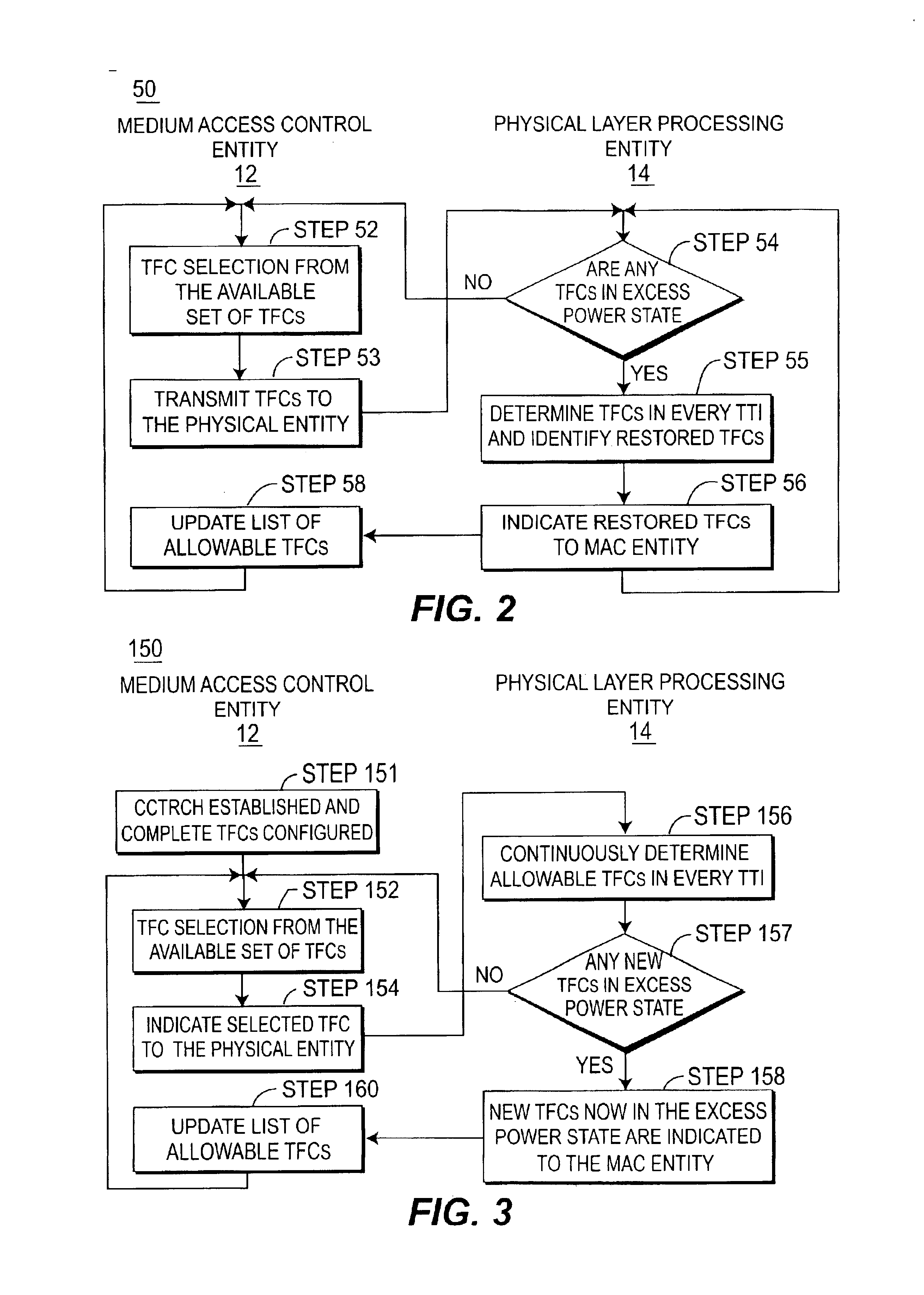
Secondly, the present invention supports efficient recovery of TFCs in the TFCS when the maximum power condition no longer exists.

Finally, the invention supports advance determination of non-supported TFCs; i.e. those TFCs that require transmission power greater then the maximum or allowed UE transmission. Thes...


PUM


Abstract

The present invention discloses a method and system for enabling efficient reduction of TFCs in the TFCS to achieve desired transmission, while remaining within desired power and data requirements. Upon the UE transmission power requirement exceeding the maximum or allowable transmission power the MAC shall be informed for subsequent TFC selection of all TFCs that currently exceed this limit. The UE will then chose the TFC with the next lower transmission power requirement and the sequence will continue until an acceptable TFC is determined. The present invention also enables the replacement of the TFCs in the TFCS and advanced determination of non-supported TFCs. The TFCs that require transmission power greater then the maximum or allowed UE transmission power shall be determined continuously in every TTI, not just in TTIs where the maximum power has been exceeded.

Description

FIELD OF INVENTIONThe present invention is related to the field of wireless communications. More particularly, the invention is directed to a system and method for fast dynamic link adaption in third generation wireless communication systems.BACKGROUNDIn Third Generation (3G) communication systems, Dynamic Link Adaptation (DLA) is used to compensate for degraded radio propagation conditions that would require the User Equipment (UE) to transmit at a transmission power greater then the maximum allowed, or physical maximum, transmission power. Transmissions that require to be transmitted at a power level greater than the maximum power level are transmitted at the maximum power level in 3G communication systems. When these signals are transmitted at the maximum power level (which is less than their desired transmit power level) they experience degraded performance and have increased error rates, increasing the likelihood that the transmitted data will not be received, and that the syst...

Claims


Application Information

Patent Timeline
Patent Type & Authority Patents(United States)
IPC IPC(8): H04B7/005H04Q7/38H04B7/26H04B7/216H04J3/16H04W52/22H04W52/36H04W52/50
CPCH04W52/223H04W52/262H04W52/30H04W52/367H04W52/50Y02B60/50Y02D30/70H04B7/2612
Inventor TERRY, STEPHEN E.DIFAZIO, ROBERT A.DICK, STEPHEN G.LEVY, JOSEPH S.
Owner RAKUTEN GRP INC
Why Eureka
Try Eureka