Spacer grid with hybrid flow-mixing device for nuclear fuel assembly

a technology of nuclear fuel and flow mixing device, which is applied in the field of spacer grids, can solve the problems of contaminating the nuclear reactor, non-uniform distribution of coolant temperature in the channel, and paralysis of heat transfer

Inactive Publication Date: 2005-01-18
KOREA ATOMIC ENERGY RES INST +1
View PDF11 Cites 11 Cited by
  • Summary
  • Abstract
  • Description
  • Claims
  • Application Information

AI Technical Summary

Benefits of technology

The primary vane set is protruded upwardly from the strap, which consists of a trapezoidal shape base of a primary vane stand and two bent primary mixing vanes on both sides, primarily to generate cross flow between channels. The secondary vane set is protruded upwardly from the strap, which consists of a trapezoidal shape base of secondary vane stand and two bent secondary mixing vanes on both sides, primarily for swirl flow generation within the channels. The two kinds of vane sets are alternatively arranged along each strap. The hybrid flow-mixing device induces a complex but effective flow pattern in fuel rod cooling, such as cross flow, swirl flow, and turbulent flow, downstream from the spacer grid

Problems solved by technology

Typically, the fuel rods emit different thermal outputs due to a non-uniform neutron flux distribution in the reactor core, and accordingly, the coolant temperatures in the channels are also non-uniformly distributed.
Dryout is a sudden increase in wall temperature, approaching a melting point, which results from a paralysis of heat transfer due to the generated vapor bubbles covering the heated surface and blocking of coolant supply adjacent to the surface.
In such a case, the local overheating area in the fuel rod cladding is fused, allowing the radioactive materials restrained inside to leak into the core and consequently contaminating the nuclear reactor.
First, violent eddies and turbulence are generated just downstream from the spacer grid, which are always present where the fluid flow encounters a blunt obstacle, but the pattern decays very quickly.
Second, lateral or cross flow occurs due to a flow deflection toward neighboring channels, and is also limited to within a short distance from a flow deflector, the shape of which determines flow magnitude and direction.
Third, swirl motion occurs within channels but becomes attenuated farther along the flow.
On the other hand, adopting the flow-mixing device in the space grid inevitably brings an increase of pressure drop.
In addition, excessive or sudden blocking by the mixing device may cause violent and unsteady eddies and in turn fuel rod vibration.
In such a case, a continuous contact slip between fuel rods and the spacer grid may generate wear problems.

Method used


Image

  • Spacer grid with hybrid flow-mixing device for nuclear fuel assembly
  • Spacer grid with hybrid flow-mixing device for nuclear fuel assembly
  • Spacer grid with hybrid flow-mixing device for nuclear fuel assembly

Examples


Embodiment Construction

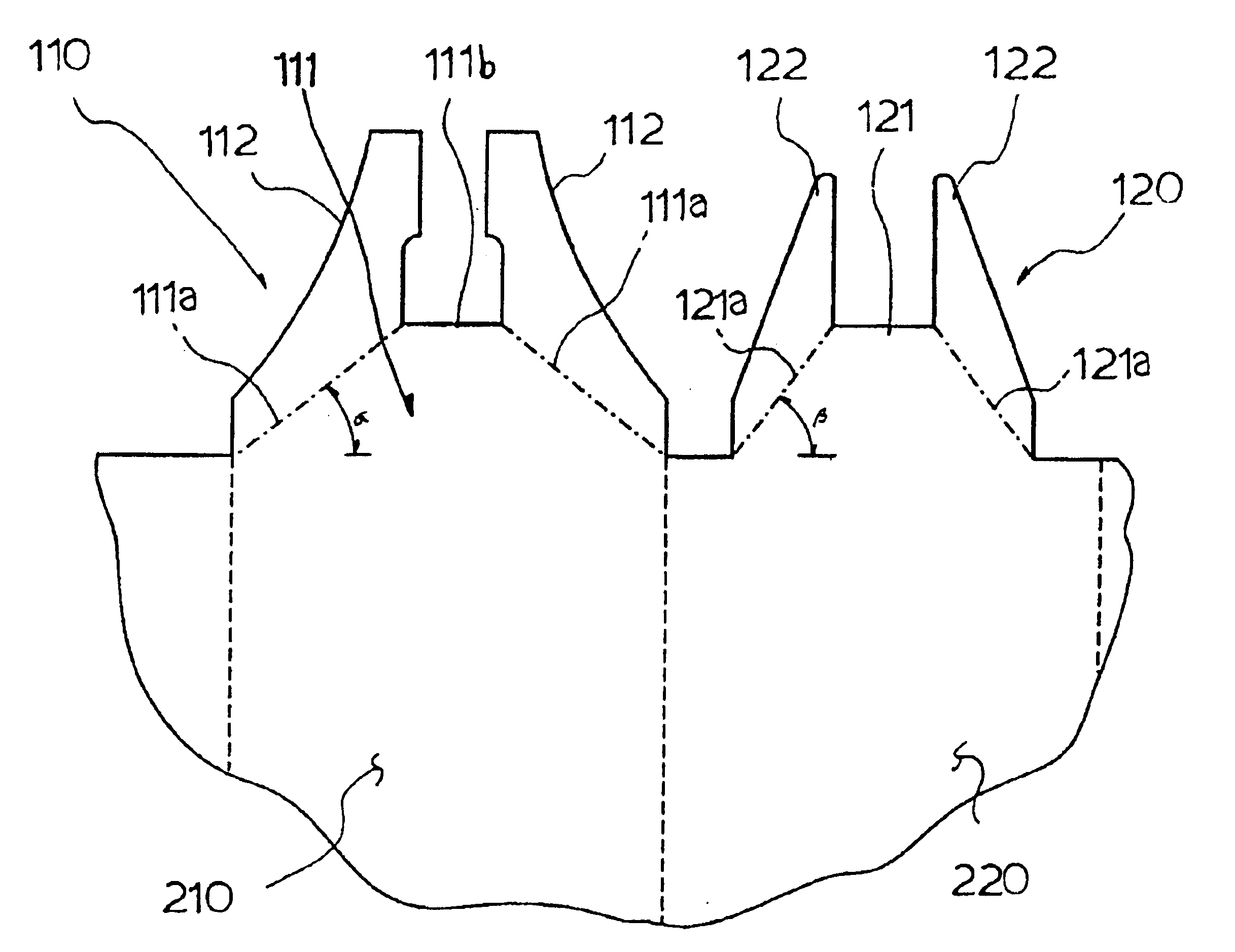
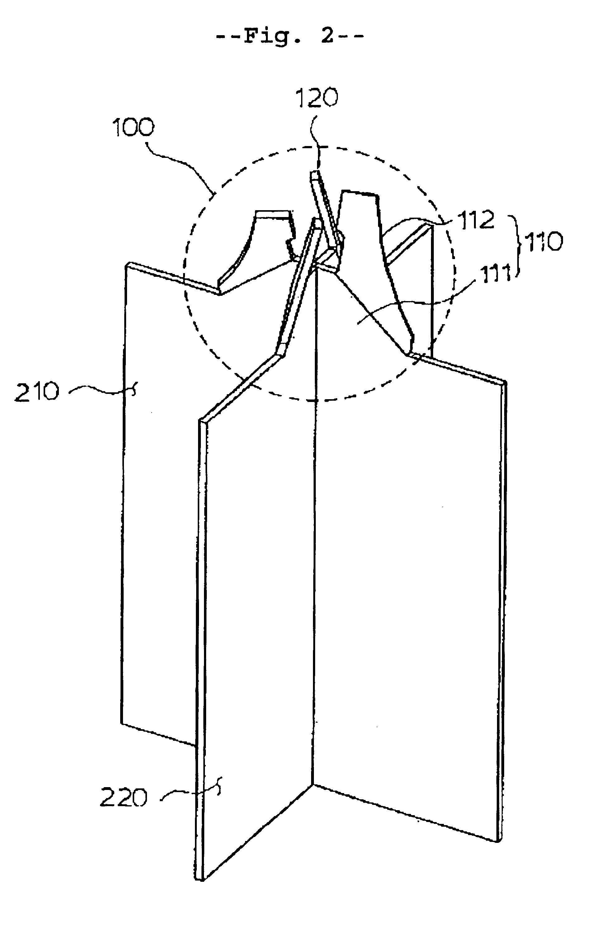
This invention is related to the flow-mixing device on the top of intersected strap junctions in the spacer grid for the nuclear fuel assembly as shown in FIG. 1. FIGS. 2, 3, and 4 show a hybrid flow-mixing device on a strap junction in different directions. As depicted in FIG. 5, each strap is composed of two types of strap units, called a primary strap unit and a secondary strap unit, and alternately arranged along the strap. The primary strap unit 210 is a strap section having a primary vane set 110 and a secondary strap unit 220 is a strap section having a secondary vane set 120. As shown in FIG. 6, the straps intersect at right angles, and the primary and secondary strap units 210 and 220 form the intersections. A hybrid flow-mixing device 100 is formed around the top of each intersection.

The object of the primary vane set 110 is mainly to take place the forced cross flows of coolant from its channel to neighboring channels in the fuel bundle. As shown in FIG. 5, this primary v...


PUM


Abstract

A spacer grid with hybrid flow-mixing devices for nuclear fuel bundle is made up of an intersection of a plurality of thin straps at right angles to form a plurality of cells for receiving and supporting fuel rods. Each strap is composed of two types of strap units, called a primary strap unit and a secondary strap unit, which are alternately arranged along the strap. The primary strap unit is a strap section having a primary vane set, and a secondary strap unit is a strap section having a secondary vane set. The straps intersect such that, by primary and secondary strap units, each intersection forms a hybrid flow-mixing device around the top of each junction. The primary vane set, consisting of a trapezoidal primary vane stand and two bent primary mixing vanes on both sides, protrudes upwardly from the strap and is primarily for generating cross flow between channels. Meanwhile, the secondary vane set, consisting of a trapezoidal secondary vane stand and two bent primary mixing vanes on both sides, also protrudes upwardly from the strap, but is primarily for swirl flow generation within the channels. The hybrid flow-mixing device induces a complex but effective flow pattern in flow channels for fuel rod cooling.

Description

BACKGROUND OF THE INVENTION1. Field of the InventionThe present invention relates, in general, to spacer grids used for supporting a plurality of fuel rods in a nuclear fuel assembly and, more particularly, to a spacer grid provided with a hybrid flow-mixing vane at the top of each intersection of inner straps, thus improving the efficiency of heat removal from nuclear fuel rods through flow mixing in coolant channels.2. Discussion of the Related ArtAs shown in FIG. 1, a contemporary fuel assembly for nuclear reactors has a square cross-section and includes a plurality of fuel rods. The fuel rods are regularly arranged by several spacer grids positioned along the axial direction.The spacer grids for the above nuclear fuel assembly are normally fabricated by intersecting at right angles a plurality of thin straps, each having a height of about 4 cm, at their vertical slits to form a plurality of four-walled cells for receiving the fuel rods. In each strap of the spacer grid, the vert...

Claims


Application Information

Patent Timeline
Patent Type & Authority Patents(United States)
IPC IPC(8): G21C3/332G21C3/33G21C3/322G21C3/34
CPCG21C3/332Y02E30/40Y02E30/30G21C3/34
Inventor CHUN, TAEHYUNOH, DONGSEOKIN, WANGKEESONG, KEENAMKIM, HYUNGKYUKANG, HEUNGSEOKYOON, KYUNGHOJUNG, YOUNHO
Owner KOREA ATOMIC ENERGY RES INST
Why Eureka
Try Eureka