Method of verifying defect management area information of optical disc

a technology of defect management area and optical disc, which is applied in the direction of digital signal error detection/correction, instruments, recording signal processing, etc., can solve the problem of not being compatible with both recording and reproducing apparatuses

Inactive Publication Date: 2005-01-18
SAMSUNG ELECTRONICS CO LTD
View PDF16 Cites 8 Cited by
  • Summary
  • Abstract
  • Description
  • Claims
  • Application Information

AI Technical Summary

Benefits of technology

To solve the above problem, a first object of the present invention is to provide a method of verifying that defect management area (DMA) information on a disc is correctly recorded and updated in an optical disc recording and reproducing apparatus which detects defects on the disc and records information on the defects in a DMA.
A second object of the present invention is to provide a method of verifying that defect management area (DMA) information on a disc is correctly recorded and updated in a recording and reproducing apparatus for repeatedly recordable and reproducible DVD-RAM discs, which detects defects on the disc and records information on the defects in the DMA.
A third object of the present invention is to provide a method of verifying that an optical recording and reproducing apparatus always reads and processes defect information properly, under the same conditions without being influenced by an actual state of a disc having defect information, using a test disc containing predetermined defect information which does not have any relation with actual defects.

Problems solved by technology

Since such DMA information is closely related to a physical data recording position, a recording medium such as an optical disc, which can be used in a given recording and reproducing apparatus even if the DMA information on the disc has been generated or updated in another recording and reproducing apparatus, may not be compatible with both recording and reproducing apparatuses when the DMA information is wrong.

Method used


Image

  • Method of verifying defect management area information of optical disc
  • Method of verifying defect management area information of optical disc
  • Method of verifying defect management area information of optical disc

Examples


Embodiment Construction

Reference will now made in detail to the present preferred embodiments of the present invention, examples of which are illustrated in the accompanying drawings, wherein like reference numerals refer to the like elements throughout. The embodiments are described below in order to explain the present invention by referring to the figures.

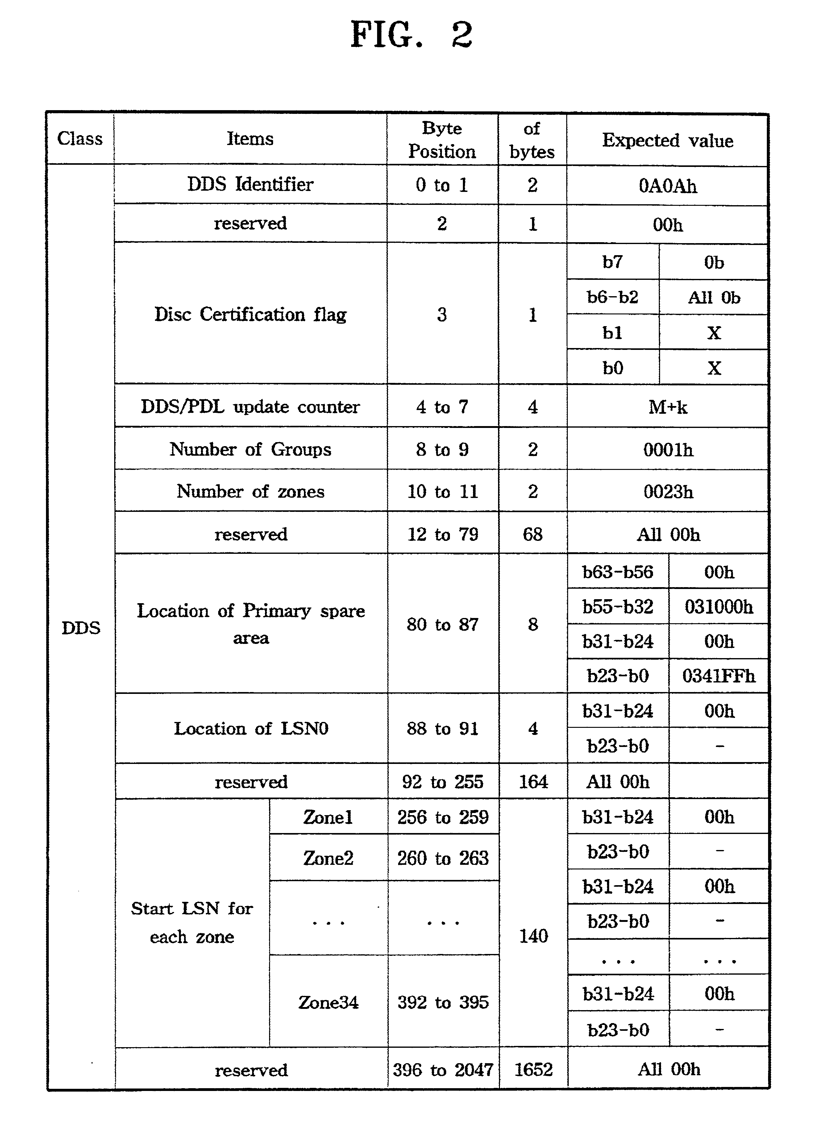
An optical disc used in the present invention is a phase change recording DVD-RAM disc having a capacity of 4.7 gigabytes (GB). DVD-RAM discs are defined in the “DVD Specification for Rewritable Discs Version 2.0.”

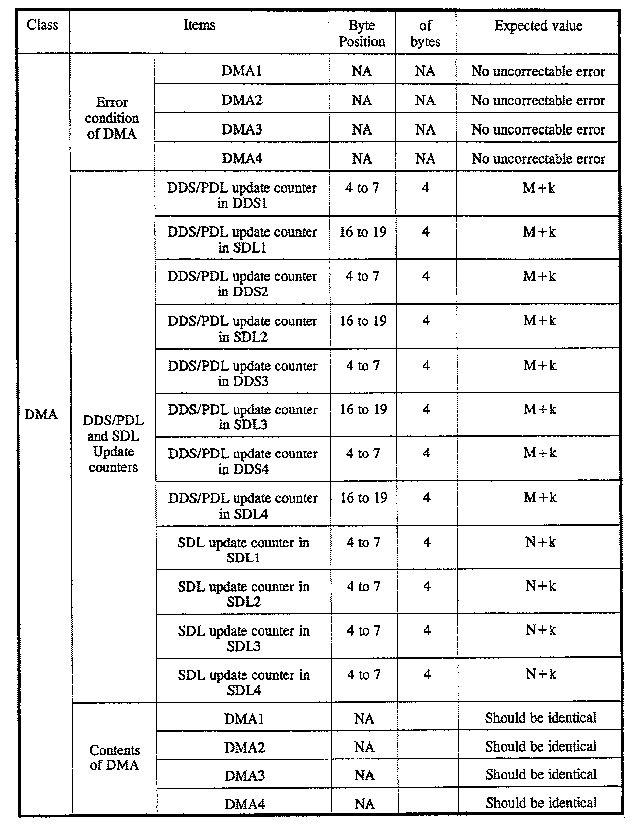
In the case of a DVD-RAM disc, every defect management process is supposed to be performed by a drive so that the file system or the host interface can record or reproduce a file without information related to physical defect management. Accordingly, most of the drives cannot record or reproduce information in or from defect management area (DMA), and moreover, are not provided with a standard command for recording or reproducing information...


PUM

PropertyMeasurementUnit
defect management areaaaaaaaaaaa
definition structureaaaaaaaaaa
primary defect listaaaaaaaaaa

Abstract

A method of verifying the defect management area (DMA) information of an optical disc. The method verifies that DMA information is properly generated or updated after a recording and reproducing apparatus, which records or reproduces information on or from an optical disc with DMA information, performs a process in a test mode for testing the generation or update of DMA information. The method includes reading the generated or updated DMA information and verifying the generated or updated DMA information using reference DMA information which is predetermined for the test mode and providing the verified result. Accordingly, it is easily verified that the recording and reproducing apparatus exactly generates or updates defect information by performing various test modes using different test discs having predetermined defect information, which has no relation with actual defects, instead of using a disc having the actual defects.

Description

BACKGROUND OF THE INVENTION1. Field of the InventionThe present invention relates to optical disc recording and reproducing technology, and more particularly, to a method of verifying the defect management area information of a recordable and reproducible optical disc.2. Description of the Related ArtDigital versatile disc-random access memory (DVD-RAM) discs have a defect management function of replacing defective areas with normal recordable areas, and storing information necessary for management of the defective areas in a portion referred to as a defect management area (DMA) thereon. The DMA is repeatedly recorded in four portions on a disc: two portions in a lead-in area and two portions in a lead-out area. DMA information includes a disc definition structure (DDS), a primary defect list (PDL) and a secondary defect list (SDL).The DMA information includes information on a spare area and important information on the start logical sector number of each zone, in addition to inform...

Claims


Application Information

Patent Timeline
Patent Type & Authority Patents(United States)
IPC IPC(8): G11B27/36G11B20/18G11B20/12G11B19/04G11B7/004G06F3/06G11B20/10
CPCG11B19/04G11B20/1816G11B27/36G11B20/1883G11B2220/20
Inventor KO, JUNG-WANCHUNG, HYUN-KWON
Owner SAMSUNG ELECTRONICS CO LTD
Why Eureka
Try Eureka