Variable resistance sensor with common reference leg

a resistance sensor and variable technology, applied in the direction of resistance/reactance/impedence, liquid/fluent solid measurement, instruments, etc., can solve the problem of circuit losing its ability to discern differences in the flow rate of fluid, it takes a relatively long time for the temperature (and thus, the resistance) of the coil rsub, and the ambient temperature of the fluid flowing into the sensor conduit increases. , to achieve the effect of high flow condition

Inactive Publication Date: 2005-01-25
BROOKS INSTRUMENT
View PDF42 Cites 45 Cited by
  • Summary
  • Abstract
  • Description
  • Claims
  • Application Information

AI Technical Summary

Problems solved by technology

However, it takes a relatively long time for the temperature (and thus, the resistance) of the coils R1 and R2 to stabilize in response to a change in the rate of flow of the fluid.
However, because each of the coils R1A and R1B is set and maintained at a predetermined temperature independently of the ambient temperature of the fluid flowing into the sensor conduit, a problem arises when the ambient temperature of the fluid flowing into the sensor conduit increases.
In particular, when the ambient temperature of the fluid flowing in the sensor conduit approaches the predetermined temperature that is maintained by the upstream and downstream coils, the circuit loses its ability to discern differences in the flow rate of the fluid, and when the ambient temperature of the fluid increases beyond this predetermined temperature, the sensor is rendered inoperable.
Despite the addition of resistors R3B and R4B, a problem with the circuit of FIG. 3 is that as the ambient temperature of the fluid flowing into the sensor conduit rises, the sensor becomes less accurate because the proportional difference between the temperature of the upstream and downstream coils relative to the temperature of the ambient fluid becomes smaller.
Further, there is a problem due to drift in that the calibration of the sensor at one temperature does not necessarily allow its use at other ambient temperatures without some sort of compensation circuit.
A disadvantage of each of these circuits is that they require a close matching of corresponding circuit elements (i.e., resistors, coils, and amplifiers) in the upstream and downstream circuits.

Method used


Image

  • Variable resistance sensor with common reference leg
  • Variable resistance sensor with common reference leg
  • Variable resistance sensor with common reference leg

Examples


Embodiment Construction

Embodiments of the present invention will be understood more completely through the following detailed description which should be read in conjunction with the attached drawings.

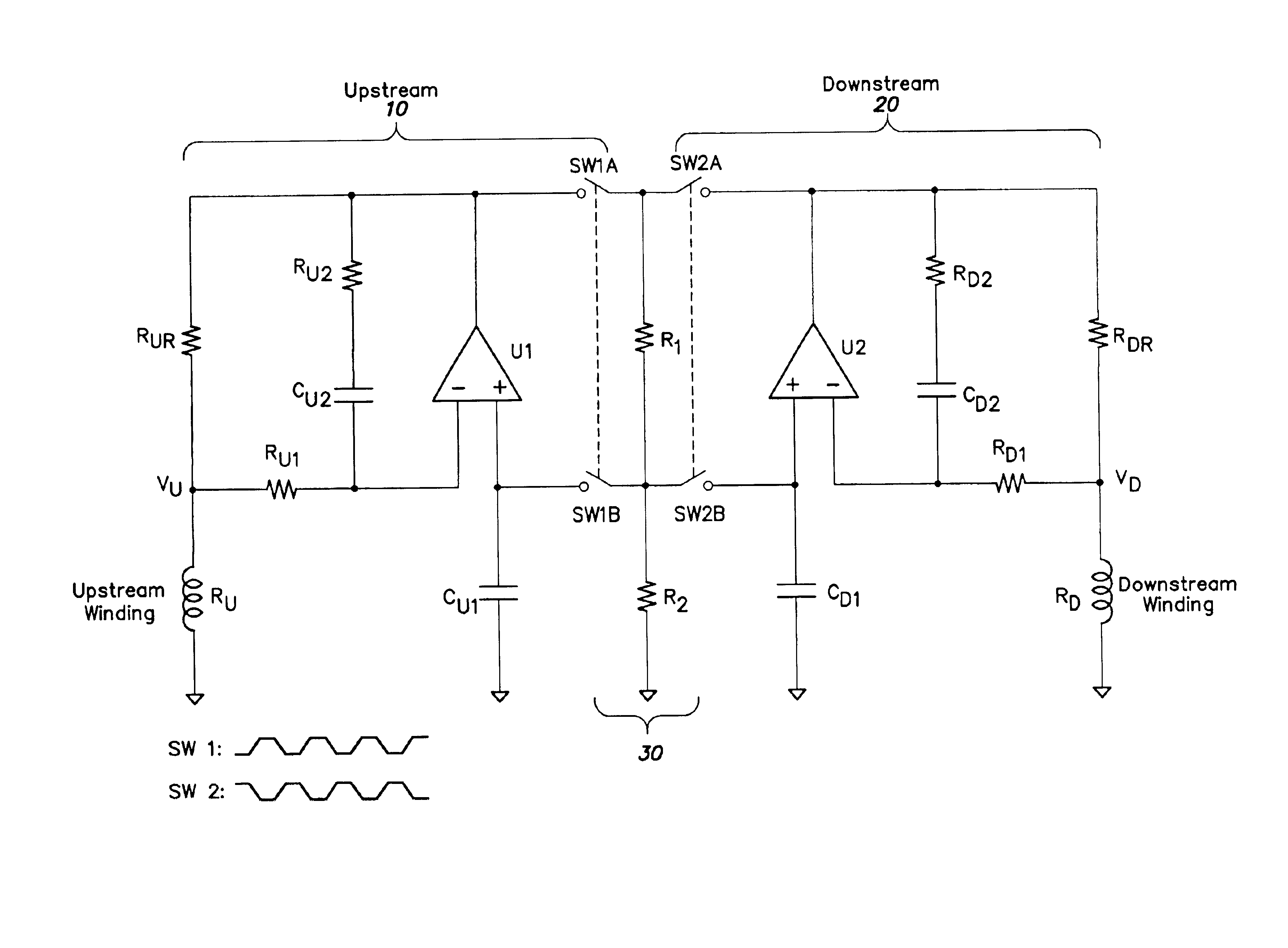
FIGS. 5, 6, 7 and 8 illustrate a number of different mass flow sensors according to various embodiments of the present invention. In each of FIGS. 5, 6, 7, and 8, the reference designator RU represents the upstream coil or resistor, and reference designator RD represents the downstream coil or resistor. As in the sensor circuits of the prior art, coils RU and RD are disposed at spaced apart positions about a sensor conduit (not shown) through which a fluid flows. As defined herein, the term fluid includes any material or combination of materials in a solid, liquid, or gaseous state.

Each of coils RU and RD has a large and substantially identical thermal coefficient of resistance, such that the resistance of each coils RU, RD varies with temperature. Although the upstream and downstream coils RU and RD are ref...


PUM


Abstract

A resistive bridge sensor circuit that includes a first resistive bridge circuit having a first variable resistance resistor and a second resistive bridge circuit having a second variable resistance resistor. The first and second resistive bridge circuits share at least a portion of a common reference leg that sets a resistance of a first and second variable resistors. The common reference leg or a portion of the common reference leg is alternately switchably connected to one of the first and second resistive bridge circuits.

Description

FIELD OF THE INVENTIONThe present invention is directed to a resistive sensor, and more particularly to a mass flow sensor having separate upstream and downstream circuits that are capable of detecting the mass flow rate of a fluid and which share at least a portion of a common reference leg.DESCRIPTION OF RELATED ARTMass flow sensors are used in a wide variety of applications to measure the mass flow rate of a gas or other fluid. One application in which a mass flow sensor may be used is a mass flow controller. In a conventional mass flow controller, the mass flow rate of a fluid flowing in a main fluid flow path is regulated or controlled based upon a mass flow rate of a portion of the fluid that is diverted into a typically smaller conduit forming a part of the mass flow sensor. Assuming laminar flow in both the main flow path and the conduit of the sensor, the mass flow rate of the fluid flowing in the main flow path can be determined (and regulated or controlled) based upon the...

Claims


Application Information

Patent Timeline
Patent Type & Authority Patents(United States)
IPC IPC(8): G01F1/684G01F1/698G01F1/696G01F1/76G01F1/86
CPCG01F1/6847G01F1/86G01F1/698G01F1/696G01F1/684
Inventor LULL, JOHN MICHAEL
Owner BROOKS INSTRUMENT
Why Eureka
Try Eureka