Glue drop end stops for zippered bag

a zippered bag and end stop technology, applied in the field of airtight zippered bags, can solve the problems of bag or zippered closure leakage, and not ensure the bag is airtigh

Inactive Publication Date: 2005-01-25
GLUE DOT COM LLP
View PDF45 Cites 65 Cited by
  • Summary
  • Abstract
  • Description
  • Claims
  • Application Information

AI Technical Summary

Problems solved by technology

Many of these prior art end stops for zippered closures deform or penetrate the ends of the bag or the zippered clos

Method used


Image

  • Glue drop end stops for zippered bag
  • Glue drop end stops for zippered bag
  • Glue drop end stops for zippered bag

Examples


Embodiment Construction

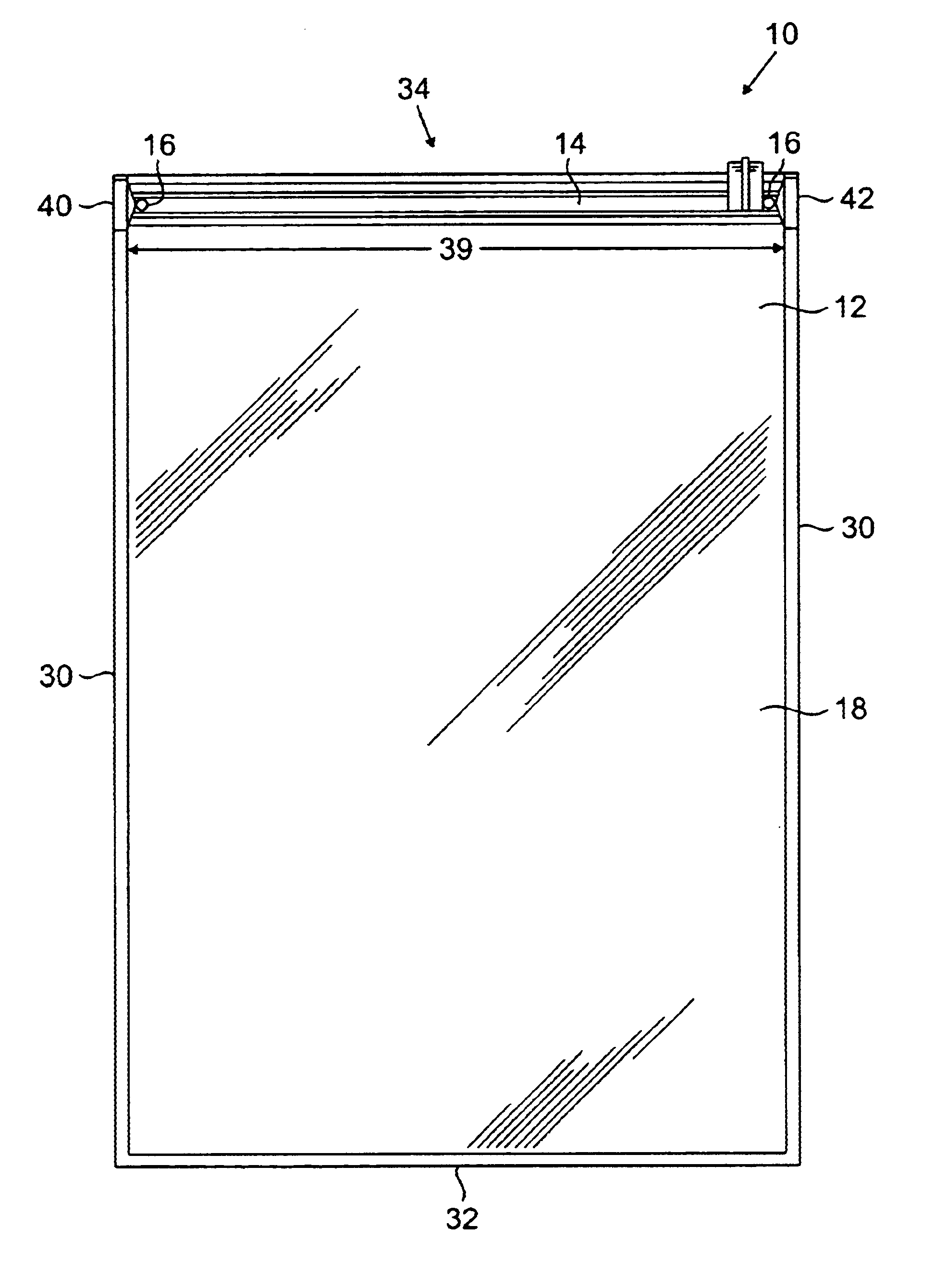
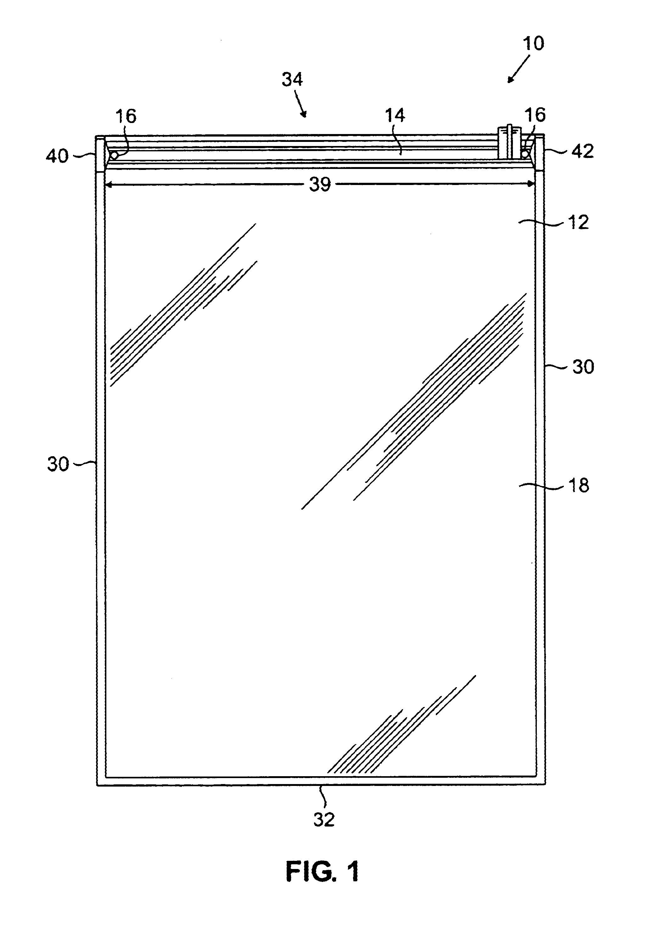
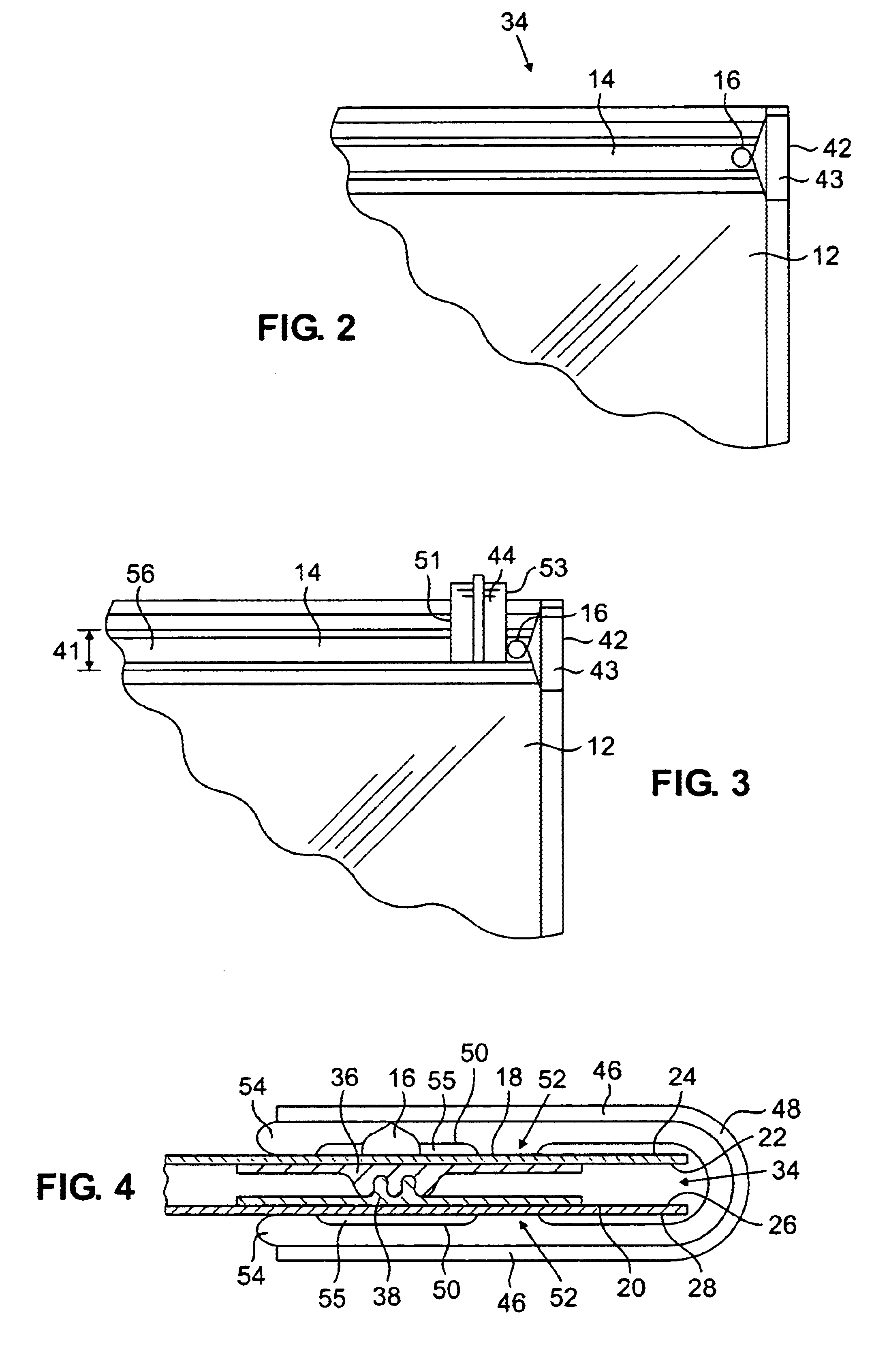
FIG. 1 shows a bag assembly 10 made in accord with an embodiment of the present invention. The bag assembly 10 includes a bag 12, a zippered closure 14, and a pair of drops 16 that act as end stops. The bag 12 is formed from a front layer 18 and a back layer 20. The front layer 18 has an inner surface 22 and an outer surface 24. The back layer 20 has an inner surface 26 and an outer surface 28 (FIG. 4).

The front layer 18 and back layer 20 are preferably placed in registration and sealed along their side edges 30 and bottom 32 to form the bag 12. Any suitable means to seal the front layer 18 and back layer 20 may be used, but they are preferably heat sealed. The bag 12 has a mouth 34 which is not heat sealed.

The front layer 18 and back layer 20 may be a monolayer structure or a multiple layer structure. The multiple layer structures can be formed by coextrusion, extrusion, lamination, extrusion lamination, or other processes well known in the art. The front layer 18 and back layer 20...


PUM


Abstract

The present invention provides a provides an airtight bag that includes a bag having a mouth and an outer surface. The bag further includes a zippered closure at the mouth, the zippered closure having a first end and a second end, and a first drop on the outer surface of the bag at one of the first end or the second end of the zippered closure.

Description

BACKGROUND OF THE INVENTIONThe present invention relates to airtight zippered bags, and more particularly, to end stops for sliders used in connection with such bags. It is known to use airtight plastic bags and containers to conveniently store bulky materials such as clothing and bedding. Airtight plastic bags are also known to store food and other materials. Examples of such airtight bags are disclosed in U.S. Pat. Nos. 6,357,915; 6,116,781; and 5,480,030, each of which is incorporated herein by reference. Airtight bags allow air to be removed from bulky items such as comforters and sweaters, and the bag sealed to essentially “shrink” the items stored inside the bag. Air can be compressed from the contents, for example, by rolling the contents,prior to closing the bag. The bags may also have a one-way valve through which a vacuum attachment can be affixed to evacuate the air from inside the bag using a conventional household vacuum cleaner. Removal of air reduces the amount of spa...

Claims


Application Information

Patent Timeline
IPC IPC(8): B31B19/62B31B19/90B31B19/00B65D33/25
CPCB31B19/62B31B19/90B65D33/2591B31B2219/6007Y10T24/2532Y10T24/45168B31B2219/9016B31B70/62B31B70/8131B65D33/259
Inventor SWEENEY, GERALDSCHWAN, HOWARDANDERSON, BRENT
Owner GLUE DOT COM LLP
Why Eureka
Try Eureka