
Caster assembly for a bed frame member or furniture

a technology of casters and bed frames, which is applied in the direction of bedstands, chairs, manufacturing tools, etc., can solve the problems of difficult to achieve the initial movement of the bed, difficult to get the swivel action to operate easily, and general difficulty in distributing the weight. , to achieve the effect of preventing severe indentation in the floor, eliminating single bending moment, and distributing weigh

Inactive Publication Date: 2005-02-15
FINGER LAKES INTPROP
View PDF25 Cites 11 Cited by
  • Summary
  • Abstract
  • Description
  • Claims
  • Application Information

AI Technical Summary

Benefits of technology

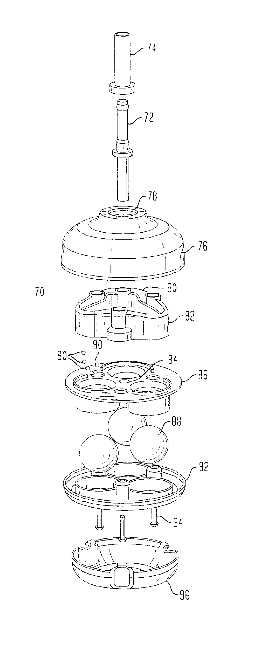
The stem has a generally vertical elongated longitudinal axis such that the weight of the bed is transmitted to the housing of the caster assembly generally along the elongated axis that is centrally located with respect to the housing. At the bottom of the caster assembly, that is, where the caster assembly is in contact with the floor, there are at least three spherical rollers that normally contact the floor and allow the bed frame to roll with respect to the floor for the convenience of moving the bed from one location to another location within a room. The spherical rollers are mounted to a housing having a cavity and a plurality of small balls are freely located between the housing and the spherical rollers such that each spherical roller is free to rotate omni-directionally, that is, the roller is mounted such that it is free to rotate about its center point and thus can rotate in any direction. As such, therefore, the roller can rotate in any direction that the user pushes the piece of furniture in relocating that piece of furniture and no additional force is needed to commence the initial movement of the furniture.
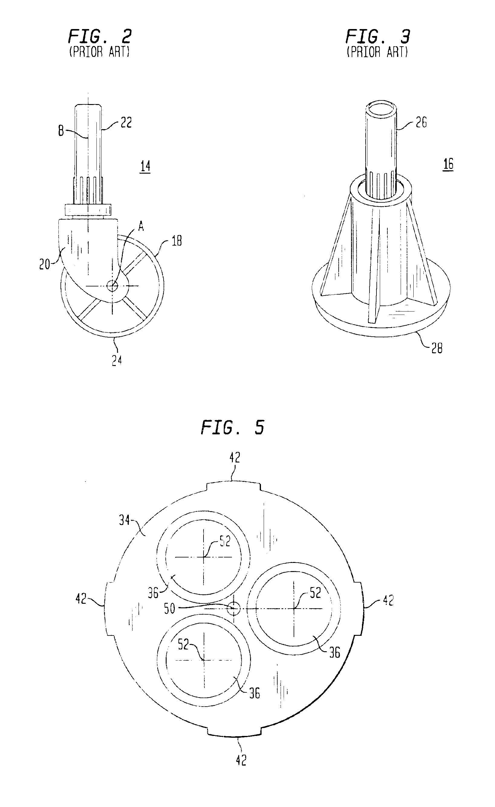
In the preferred embodiment, there are at least three spherical rollers, more preferably three rollers, so that the weight of the bed frame and its supported components and weights are distributed at three contact points with the floor to better distribute the weight and prevent severe indentation in the floor. In addition, the location of the rollers is such that they are equidistant from the elongated central axis through which the weight of the bed frame acts on the caster assembly and thus, the single bending moment is eliminated and the structure has enhanced strength and stability. As stated, with the three rollers, each is still mounted to a housing such that the rollers move freely in any direction and do not need to be aligned to the direction of movement of the furniture or bed by pivoting about a central axis. In effect, the need for a swiveling function is completely eliminated.
Accordingly, the caster assembly of the present invention has the strength of the prior art glide assemblies since the single offset has been eliminated and, of course, the assembly therefore does not need to swivel in order to allow the furniture or bed to be moved in any direction. With the offset and the need to swivel eliminated, the aforedescribed problems associated with those features are also eliminated.
The resulting caster assembly therefore combines the strength of the glide assemblies with the mobility of a roller caster assembly and provides the user with the option of using the spherical rollers to contact the floor or easily transform the caster assembly to add a glide so that the assembly can be used on slippery surfaced floors.

Problems solved by technology

The swiveling action or movement is necessary to correctly align the roller for movement in the proper direction, however, such swiveling movement can be generally difficult to accomplish.
With the weight of the mattress and box spring there is considerable friction acting against the swiveling action of the caster assembly and the problem is aggravated by the need to align some 4-5 rollers in order to roll the bed frame.
As such, therefore, while the swivel action is necessary to properly move the bed or other furniture, it can be somewhat difficult to get the swivel action to operate easily and thus the initial movement of the bed is not easy to accomplish, particularly when the bed is on carpeting with padding.
One of the difficulties with such casters, therefore, is that the bending moment created by that offset causes stress on the caster assembly and can cause a premature failure of the caster assembly or the bed frame leg itself, thereby disabling the entire unit.
In the aforementioned patents, however, while a plurality of members contact the floor and thus allow the weight to be borne by a plurality of elements, there is a further problem with respect to the ease of moving such casters as the spherical members are clamped into the housing supporting the particular piece of furniture and the spherical contact members do not thus freely rotate to allow the ready movement of the furniture.
With such flooring surfaces, the user of a caster having a roller causes unnecessary sliding or rolling as contrasted to the intended use of a rug roller or caster on a carpeted surface where the friction with the carpet reduces the mobility of the roller or caster.
With such side rails, however, the use of a glide to support a cross member has certain problems, that is, the strength of a glide is needed, yet there is also needed some mobility so that the bed rail type of bed can be moved from one location within a room to another location.
In moving the bed rail type of bed, with a center adjustable glide, the glide can catch on the floor, particularly with a carpet, and thus twist the cross member and cause breaking of the leg itself.
In general, all such cross member supports in the prior art utilize a glide in view of its strength, but take along with that asset, the problem of the glides lack of mobility, particularly when moved along a carpeted floor.
The caster cups, however, are easily displaced from under the roller since they are not firmly locked to or attached to the caster assemblies and are thus difficult to maintain in place when the furniture is moved during the normal use of the furniture.
Thus, over time, the caster cups become displaced with respect to the roller and no longer serve their intended purpose.

Method used


Image

  • Caster assembly for a bed frame member or furniture
  • Caster assembly for a bed frame member or furniture
  • Caster assembly for a bed frame member or furniture

Examples


Embodiment Construction

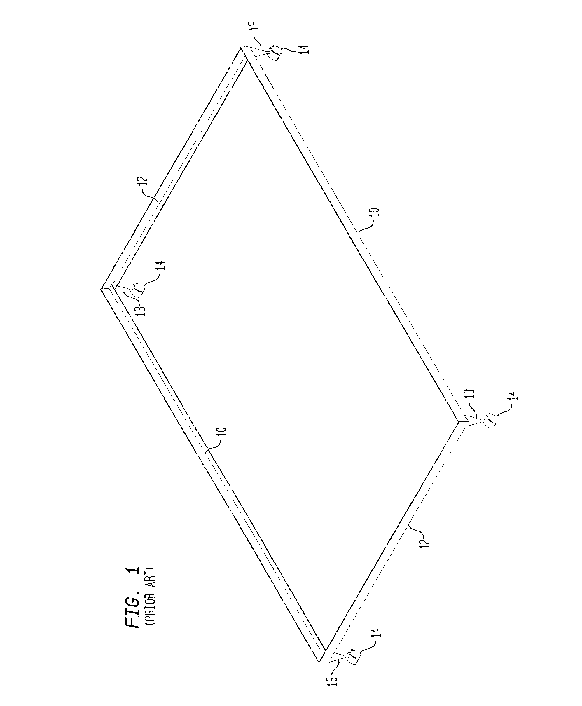
Referring now to FIG. 1, there is shown a perspective view of a conventional bed frame with which the present invention can be applied. It should be noted, however, that while the FIG. 1 embodiment of the present invention is initially shown and described specifically for use with a bed frame, the broader aspects of the invention make it applicable to any item of furniture with the same advantages and improvements.

Thus, in FIG. 1, the conventional bed frame is comprised of a pair of side rails 10 and cross members 12. The number of cross member may vary depending upon the particular bed, and its size, that is, there may be one or more intermediate cross members that provide additional support to the box spring and mattress when assembled. The side rails 10 and cross members 12 are normally constructed of L-shaped angle iron. As shown, there are legs 13 that are normally located on the cross members 12 or the side rails 10 depending on the particular construction and, if any further ...


PUM


Abstract

A caster assembly that can be used with furniture to support the furniture and to make the furniture mobile. The caster assembly has a housing with a stem that extends upwardly to be attached to the particular piece of furniture. Within the housing is a plurality of spherical rollers that are supported within the housing so as to be rotatable about their center points and therefore can rotate in any direction as the furniture is moved. In the preferred embodiment, there are three spherical rollers that are all equidistant from the center line or longitudinal axis of the stem so that the weight of the furniture that bears down upon the stem is supported equally by the spherical rollers contacting the floor. As a further feature, a glide cup is provided that can be readily attached and detached from the bottom of the housing and, whet attached, the glide cup covers the spherical rollers and presents a flat, planar surface that contacts the floor.

Description

BACKGROUND OF THE INVENTIONThe present invention relates to a caster assembly for a use with furniture, and, more particularly, to a caster assembly adapted for use with bed rails or a bed frame including side rails and cross members and which allows the weight on the caster to be centrally positioned and further has a glide that can be easily attached and / or detached from the caster assembly.In general, bed frames are well known and are comprised of various structural members such as side rails and cross members that interconnect the side rails and provide a relatively rigid structure of predetermined dimensions in order to support a box spring and a mattress. The common side rail member and cross member is an L-shaped steel member with various manners of connecting the individual components together.The components, that is, the side rails and the cross members also are generally provided with legs that extend downwardly toward the floor so that the components are elevated from the...

Claims


Application Information

Patent Timeline
Patent Type & Authority Patents(United States)
IPC IPC(8): A47C19/00A47C19/02A47C7/00B60B33/00
CPCA47C19/024B60B5/02B60B33/001B60B33/0021B60B33/08B60B33/0028Y10T16/188Y10T16/1889Y10T16/1853Y10T16/216
Inventor POLEVOY, RICHARDRYAN, HOWARD SCOTTCARLSON, PAUL ERIC
Owner FINGER LAKES INTPROP
Learn More