Engine body and cylinder for internal combustion engine

Inactive Publication Date: 2005-02-15
HUSQVARNA AB
View PDF9 Cites 4 Cited by
  • Summary
  • Abstract
  • Description
  • Claims
  • Application Information

AI Technical Summary

Benefits of technology

The purpose of the subject invention is to achieve a crankcase scavenged two-stroke engine with scavenging ducts of such a length that a homogenous air/fuel mixture can be achieved in the scavenging ducts wit

Problems solved by technology

Nor there is need for two scavenging ducts to meet in only one connecting duct in

Method used


Image

  • Engine body and cylinder for internal combustion engine
  • Engine body and cylinder for internal combustion engine
  • Engine body and cylinder for internal combustion engine

Examples


first embodiment

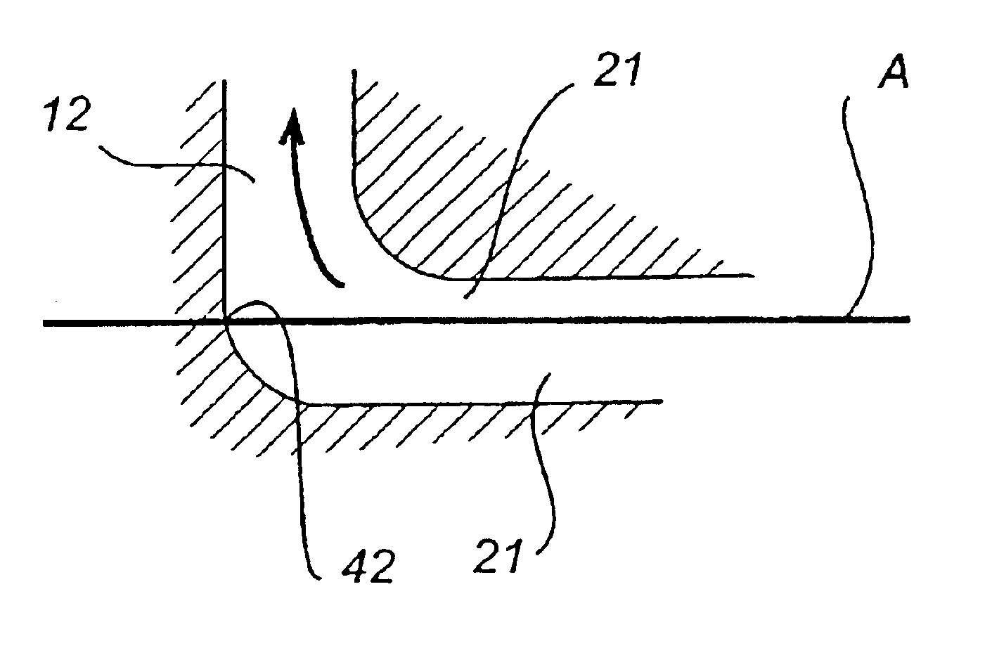
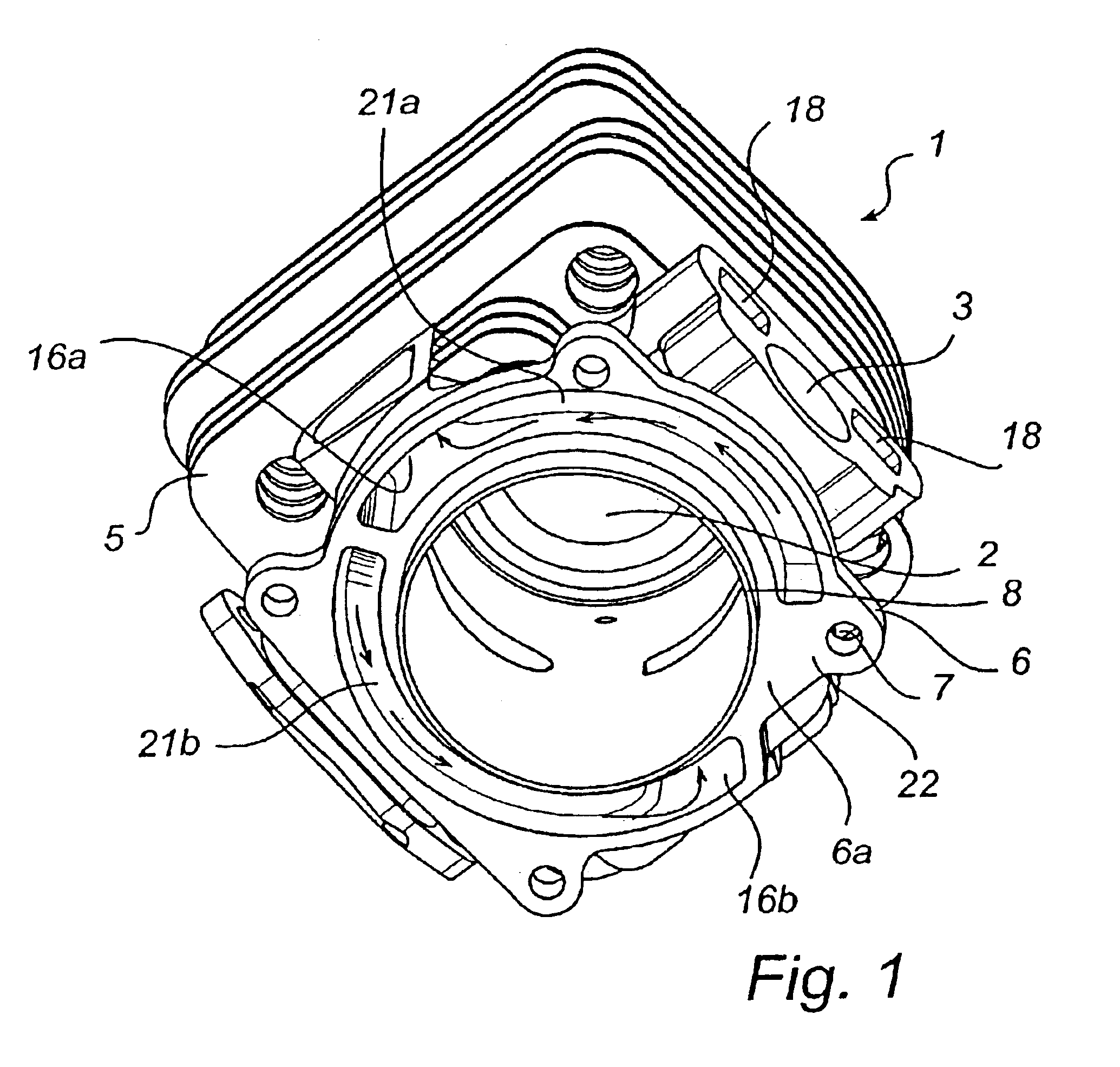
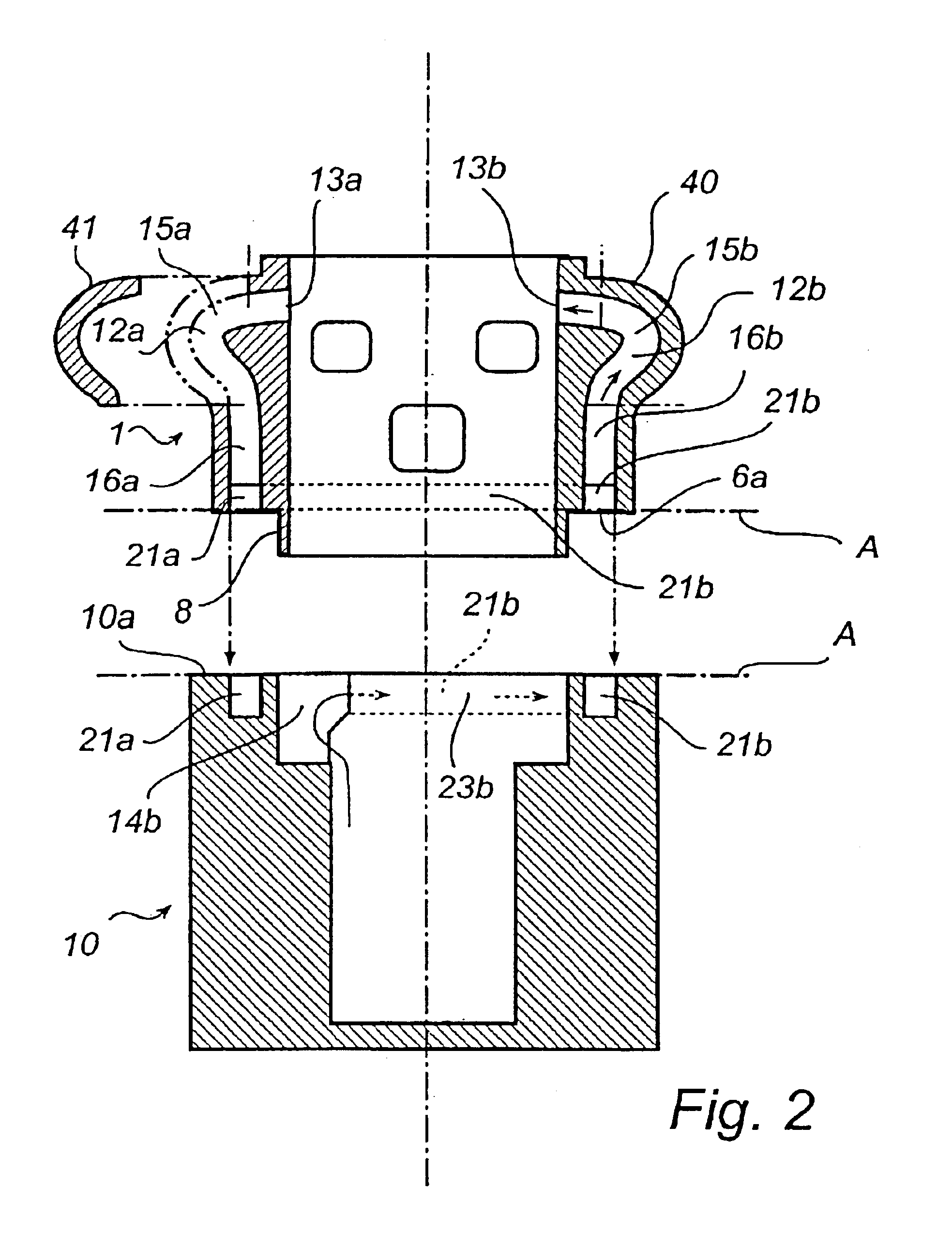
With reference to FIG. 1 a cylinder according to the invention is shown. The cylinder has a cylinder bore 2, in which a piston (not shown) is intended to be movable, an inlet 3 for air / fuel mixture adapted for connection to a carburettor via an inlet tube (not shown), as well as an exhaust outlet (hidden in the figure) adapted for connection to a muffler. The entire cylinder is surrounded by cooling fins 5, and at its lower edge a stronger flange 6 is arranged and intended, by means of attachment devices, such as bolts running through recesses 7, to be firmly connected to a crankcase. The underside 6a of the flange, which will be described in closer detail in the following, is located in an imagined parting plane A between the cylinder 1 and a at the cylinder firmly connected crankcase 10, consisting of two halves, as shown schematically in FIG. 2. The cylinder bore 2 continues a bit below the flange in that a collar 8 extends pass by the underside 6a of the flange 6. This collar 8 ...

second embodiment

According to the invention as shown in FIG. 6, a disc-shaped intermediate element 30 with penetrating apertures 31, is arranged in the parting plane A between cylinder 101 and crankcase 110. According to this embodiment depressions are arranged both in the cylinder 101 and in the crankcase 110, and they are formed in such a way that beginning 32 of a depression 33 in the cylinder 101 is arranged essentially above the end 34 of corresponding depression 35 in the crankcase 110. An aperture 31 connects the depression 33 in the cylinder 101 with the depression 35 in the crankcase 110, whereby each scavenging duct 112 extends first along a depression 35 in the crankcase 110, and then passes through the aperture 31 in the disc 30, in order to then continue in the same direction along a depression 33 in the cylinder 101. In other words, the scavenging duct 112 runs in a way like a spiral, where the disc 30 serves as a partition wall in the spiral.

The manufacturing of the cylinder 1 accordi...


PUM


Abstract

The subject invention refers to an engine body for a crankcase scavenged two-stroke engine, comprising a cylinder (1) with a cylinder bore (2), and on opposite sides of the cylinder located, closed scavenging ducts (12a, 12b), as well as crankcase (10) with at least two crankcase parts, whereby the cylinder (1) and the crankcase (10) are connected to each other in a mutual parting plane (A) essentially perpendicular towards the longitudinal axis (B) of the cylinder bore (2). The engine body is characterized in that said scavenging ducts (12a, 12b) are having an essentially right-angled bend for, in said parting plane (A), running in a mutual direction around the periphery of the cylinder bore (2), whereby the scavenging ducts (12a, 12b), in level with the parting plane (A), comprise depressions (21a, 21b) in at least one of the either the cylinder (1) or the crankcase (10), as well as one connecting duct (14a, 14b) each, that connect each depression (21a, 21b) with the inner space of the crankcase (10). Owing to that the scavenging ducts are running in a mutual direction around the periphery of the cylinder bore and are having one connecting duct each to the crankcase, scavenging ducts of such a length are created so that a homogenous air/fuel mixture can be achieved in the scavenging ducts without the crankcase taking too bulky proportions. The length of the scavenging ducts will also allow a satisfactory stratification of the scavenging gases for a two-stroke engine provided with additional air.

Description

TECHNICAL FIELDThe subject invention refers to an engine body for a crankcase-scavenged two-stroke engine, comprising a cylinder having a cylinder bore and closed scavenging ducts located on opposite sides of the cylinder, as well as a crankcase containing at least one crankcase part, whereby the cylinder and the crankcase are connected to each other in a mutual parting plane essentially perpendicular towards the longitudinal axis of the cylinder bore. The invention also relates to a cylinder for such an engine body.More specifically the invention refers to a die-cast engine body and cylinder.BACKGROUND OF THE INVENTIONA difficulty regarding crankcase-scavenged engines is to provide a homogeneous air-fuel mixture to the combustion chamber. This can be achieved by so called long scavenging ducts, which however tends to make the crankcase complicated and bulky. For two-stroke engines provided with additional air to the scavenging ducts it is important to keep the air in the-scavenging...

Claims


Application Information

Patent Timeline
IPC IPC(8): F02F1/22F02B33/44F02B33/04F02B33/02F02F1/18F02B75/02
CPCF02B33/04F02F1/22F02B33/44F02B2075/025
Inventor OLANDER, ULF
Owner HUSQVARNA AB
Why Eureka
Try Eureka